Non-contact electrical energy transmission device with self-adaptive power factor correction and control method

A power factor correction and electric energy transmission technology, applied in the direction of output power conversion devices, circuit devices, electrical components, etc., can solve problems such as resonant frequency changes, system instability, and difficulty in determining control points, etc., to increase DC bus voltage , increase the output power, the effect of convenient control

Inactive Publication Date: 2011-07-20
SOUTHEAST UNIV
View PDF6 Cites 22 Cited by
  • Summary
  • Abstract
  • Description
  • Claims
  • Application Information

AI Technical Summary

Problems solved by technology

But at this time, another problem that arises is that if there are multiple zero-phase angle points in the spectrum range, it is difficult to determine the ideal control point
[0008] When the load of the non-contact power transmission system changes, it will directly lead to a change in its

Method used


Image

  • Non-contact electrical energy transmission device with self-adaptive power factor correction and control method
  • Non-contact electrical energy transmission device with self-adaptive power factor correction and control method
  • Non-contact electrical energy transmission device with self-adaptive power factor correction and control method

Examples


Embodiment Construction

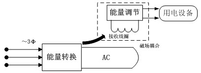
[0028] Such as figure 1 Shown is a schematic diagram of the principle of the non-contact power transmission system. It can be seen from the figure that the non-contact power transmission system can be divided into two parts, the primary circuit and the secondary circuit, and are connected to the power supply system and the load equipment respectively. Each loop stage achieves non-contact power transfer through spatially coupled magnetic fields. The function of the primary loop is to generate high-frequency current after the high-frequency inverter transformation of the power supply, and emit it in the transmitting coil. The pickup coil in the secondary loop is in the changing magnetic field of the small air gap near the transmitting coil of the primary loop. The energy is picked up, and the high-frequency electric energy is converted into the energy form required by the load equipment through the energy converter, which completes the entire non-contact energy transmission pro...


PUM


Abstract

The invention discloses a non-contact electrical energy transmission device with self-adaptive power factor correction and a control method, the device adopts the AC (alternating current)/DC (direct current)/AC (alternating current) energy conversion way, the structure of a diode rectifier bridge plus a half-bridge double-switch is used for realizing the functions of active power factor correction and resonance inversion, and the structure of a three-order resonant network is further utilized for realizing the functions of reactive power compensation and load self-adaption. The control method of the device is simple, and only a driving signal with a constant frequency and constant duty cycle needs to be imposed on the half-bridge double-switch. The problems of small output power, great harmonic pollution, poor load applicability and the like in the non-contact electrical energy transmission technology can be solved by the device and the control method, and the device and the control method can be widely used in moving and lifting equipment of plants, mining and transporting equipment of coal mines, electrical power and subway locomotives, factories and mines with flammable and explosive gas and other various occasions.

Description

technical field [0001] The present invention relates to a non-contact power transmission device and its control method, in particular to a non-contact power transmission capable of realizing resonance inversion, increasing output power, performing active power factor correction, adapting to different load conditions and maintaining system stability Device and control method thereof. Background technique [0002] At present, in the power supply system for mobile electrical equipment (such as factory mobile hoisting equipment, mine mining and transportation equipment, electric power and subway locomotives, trolleybuses, light rails and other urban passenger vehicles), the direct conduction method of contact electric energy is generally used (Including direct wire transmission method, sliding contact method and rolling contact method). There are many problems in this power transmission mode, such as exposed wires, mechanism wear, contact sparks, etc., which bring great problem...

Claims


Application Information

Patent Timeline
IPC IPC(8): H02J17/00H02M1/42H02J50/10H02J50/12
CPCY02B70/126Y02B70/10
Inventor 赵剑锋闫安心曹武
Owner SOUTHEAST UNIV
Why Eureka
Try Eureka