Cutting or welding robot

A welding robot and cutting torch technology, applied in welding equipment, auxiliary welding equipment, welding/cutting auxiliary equipment, etc., can solve the problems of high manufacturing cost, difficult manufacturing of welding groove cutting machine, etc., and achieve the effect of simple structure

Inactive Publication Date: 2011-07-27
洛阳汉鼎起重机械有限公司
View PDF8 Cites 30 Cited by
  • Summary
  • Abstract
  • Description
  • Claims
  • Application Information

AI Technical Summary

Problems solved by technology

[0003] The purpose of the present invention is to provide a cutting or welding robot to solve the problems of the prior art that the welding

Method used


Image

  • Cutting or welding robot
  • Cutting or welding robot
  • Cutting or welding robot

Examples


Embodiment Construction

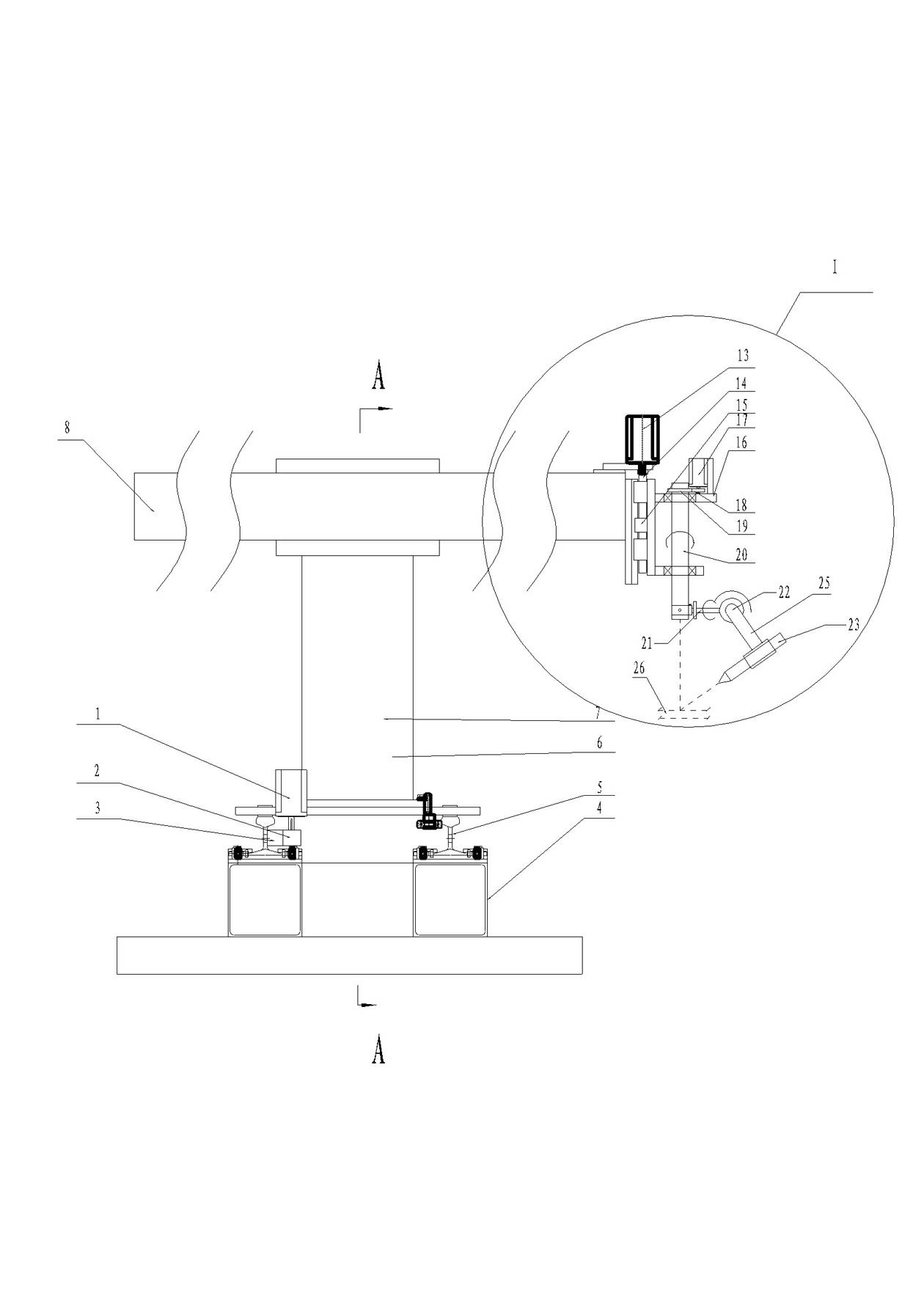
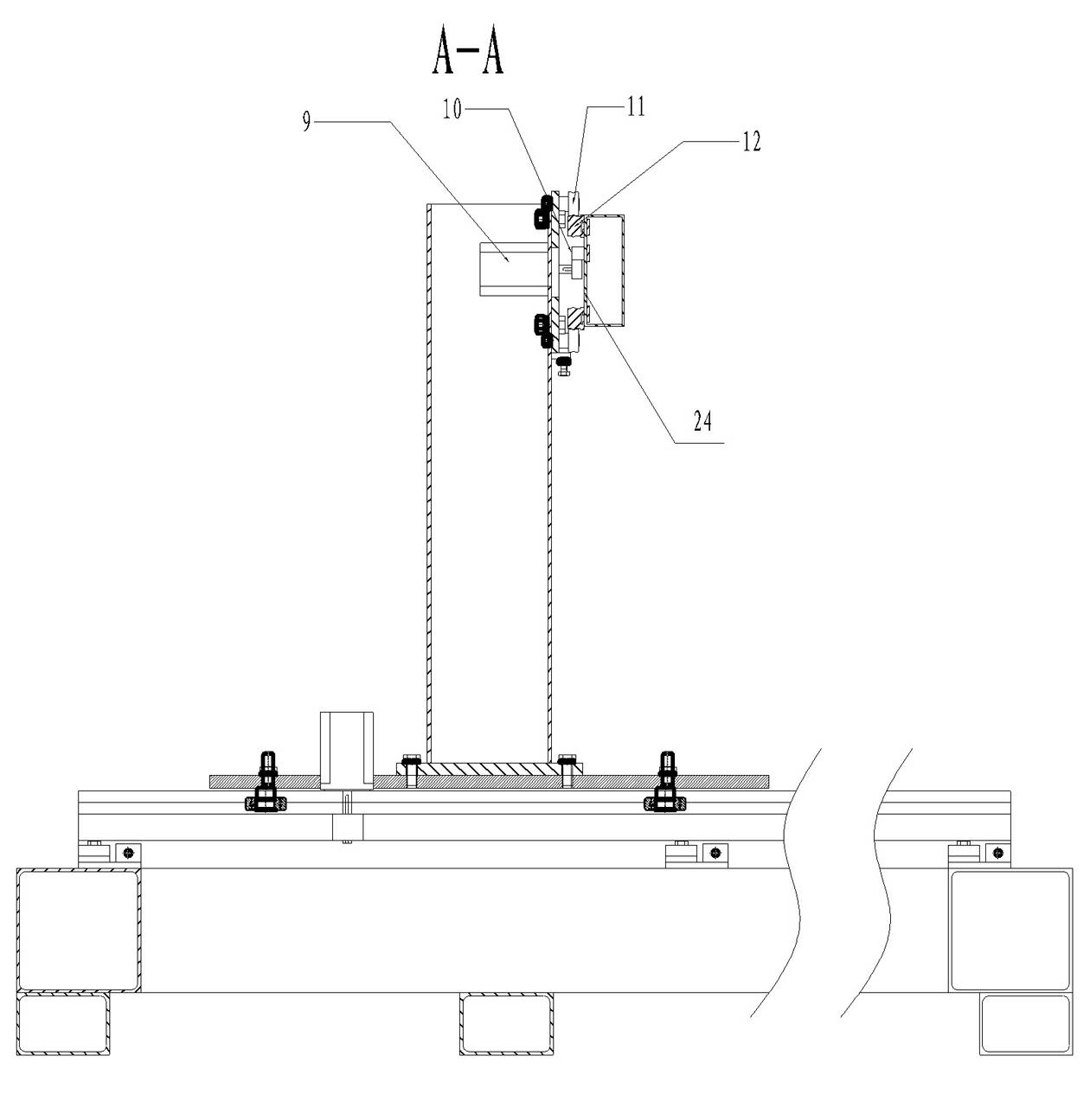
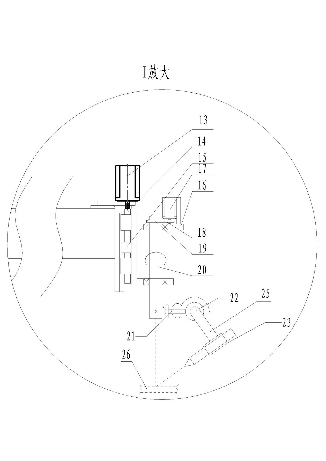
[0016] Example Figure 1~3 As shown: the cutting or welding robot includes a base 4, and the two directions perpendicular to each other on the horizontal plane are respectively defined as the X direction and the Y direction, and the vertical direction is defined as the Z direction. The upper surface of the base is along the The Y direction is provided with a cutting torch longitudinal linear motion mechanism 7, and the machine base 4 is provided with a longitudinal guide rail 5 for the assembly of the cutting torch longitudinal linear motion mechanism 7. The longitudinal guide rail 5 is provided with a longitudinal rack 3, and the first drive motor 1 passes through the second A gear 2 cooperates with the longitudinal rack 3 to realize the longitudinal linear movement mechanism 7 of the cutting torch to move in the Y direction. The longitudinal linear movement mechanism 7 of the cutting torch also includes a longitudinal slide plate 6, and the longitudinal slide plate 6 is provi...


PUM


Abstract

The invention discloses a cutting or welding robot which comprises a base; two mutually-perpendicular directions on the horizontal plane are respectively defined as an X direction and a Y direction, and the vertical direction is defined as a Z direction; a cutting-torch longitudinal linear motion mechanism and a cutting-torch transverse linear motion mechanism are respectively arranged on the base in two mutually-perpendicular horizontal directions, and the cutting-torch longitudinal linear motion mechanism or the cutting-torch transverse linear motion mechanism is provided with a cutting-torch lifting device; the cutting or welding robot also comprises a robot head which is used for cutting or welding workpieces; and the cutting-torch lifting device is provided with an installation base, the installation base is provided with a cutting-torch rotation shaft which is arranged in the Z direction and can rotate freely, and the robot head is arranged at the lower part of the cutting-torch rotation shaft. By utilizing the cutting or welding robot, the problems that in the prior art, because an unlimited turning working dish is required to be added, the manufacturing difficulty of the cutting or welding robot is large, and the manufacturing cost is high are solved.

Description

technical field [0001] The invention relates to the field of industrial cutting and welding, in particular to a cutting or welding robot. Background technique [0002] According to the workpiece welding groove cutting machine disclosed in Chinese patent 200910143483.X "Workpiece Welding Groove-Workpiece Rotary CNC Cutting Machine Processing Method", the workpiece welding groove cutting machine includes a machine base, and the side of the machine base The longitudinal linear motion mechanism of the cutting torch is installed, and the longitudinal linear motion mechanism of the cutting torch includes a longitudinal slide plate, and an infinitely rotatable work disk is arranged on the above-mentioned machine base, and a device corresponding to the longitudinal slide plate is arranged above the infinitely rotatable work disk. The connected beam, the beam is provided with a horizontal (X) linear motion mechanism and a horizontal slide plate, and the vertical (Y) linear motion mec...

Claims


Application Information

Patent Timeline
IPC IPC(8): B23K37/00B23K37/02
Inventor 陈宏伟
Owner 洛阳汉鼎起重机械有限公司
Why Eureka
Try Eureka