Fully automatic stone face milling machine

A milling machine, fully automatic technology, applied in the direction of stone processing tools, stone processing equipment, manufacturing tools, etc., can solve the problems of large dust, single direction of thickness determination, large thickness error of products, etc., to achieve easy equipment operation and complete surface Smooth, uniform thickness

Active Publication Date: 2011-07-27
UNIVERSAL MARBLE & GRANITE DONGGUAN
8 Cites 4 Cited by

AI-Extracted Technical Summary

Problems solved by technology

[0002] In the existing technology, the traditional stone face milling machine has a single thickne...

Method used

[0014] The present invention consists of tool spindle system, tool holder, beam, base, workbench five parts. Driven by the motor, the tool holder can automatically run left and right on the beam, and the encoder counts to achieve precise positioning. The tool holder and the beam are connected by three-point positioning and a high-precision rack to achieve precise transmission. The tool spindle The system is driven by a screw nut, driven by a motor, and can automatically run up and down on the tool holder. The encoder is used for counting to achieve precise positioning; driven by the motor, the beam can automatically run back and forth on the base, and the encoder is used for co...

Abstract

The invention discloses a fully automatic stone face milling machine. The machine comprises two symmetric pedestals, wherein the pedestals are provided with guide rails; a movable cross beam and a cross beam driving mechanism are arranged on the guide rails; the cross beam is provided with a knife rest which can travel along the cross beam; and a working table is arranged between the two pedestals. A machining process of the stone face milling machine is fully and automatically controlled by inputting numerical values in a man-machine conversation mode, and the machine has unidirectional machining and multidirectional composite machining functions; the equipment is easy and convenient for operation, and different machining parameters can be set according to different product types to improve machining efficiency; energy and power are saved by adopting a variable frequency control technology; the execution is fully and automatically controlled through digital set point control and digital quantitative control, the machined product has a completely flat surface and uniform thickness, and the problem of edge breakage of the product can be solved well; and water is added to a grinding disc to a fixed thickness, so that dust is effectively eliminated and environment is protected.

Application Domain

Stone-like material working tools

Technology Topic

Automatic controlVariable frequency control +7

Image

  • Fully automatic stone face milling machine
  • Fully automatic stone face milling machine
  • Fully automatic stone face milling machine

Examples

  • Experimental program(1)

Example Embodiment

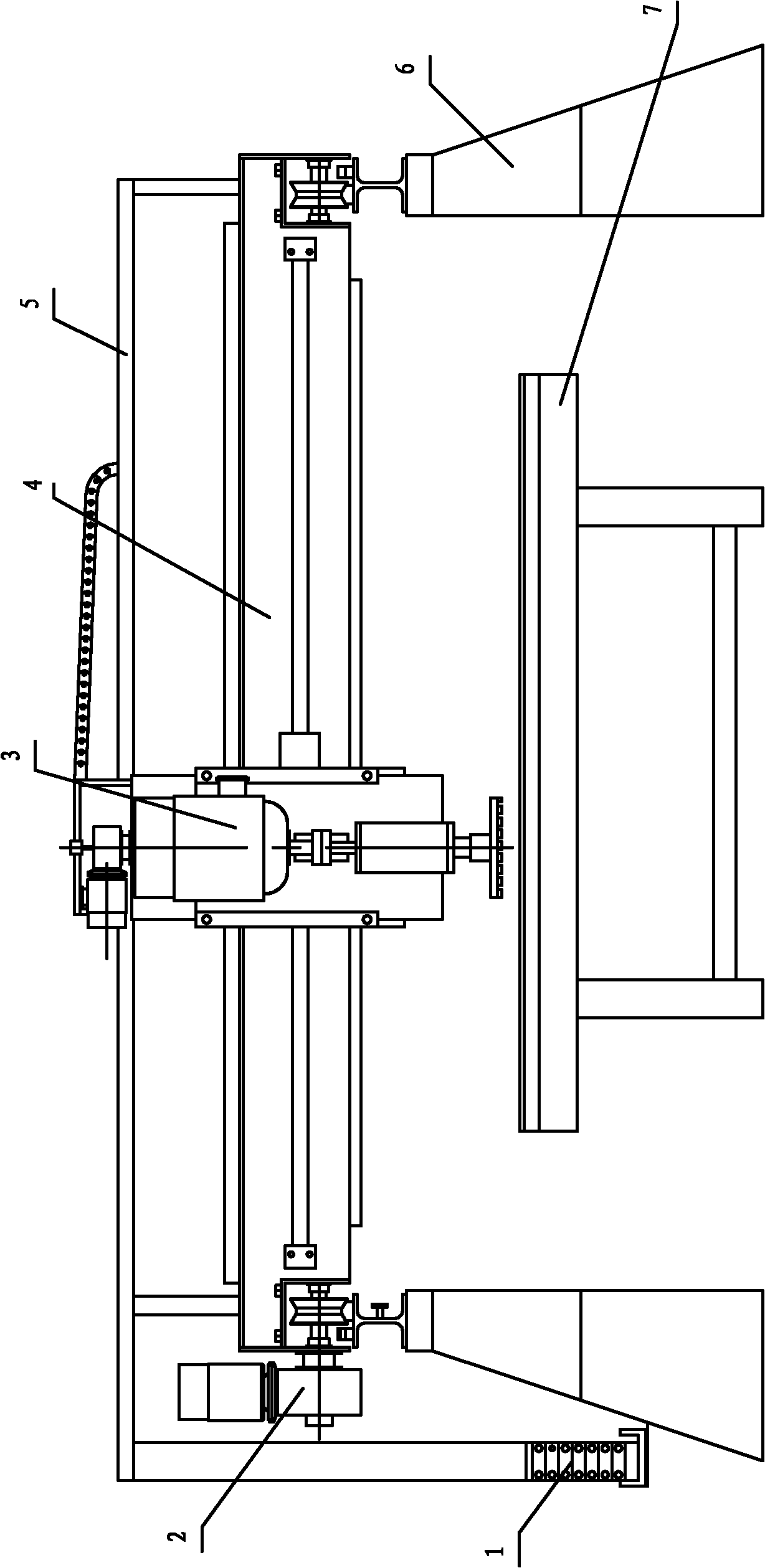
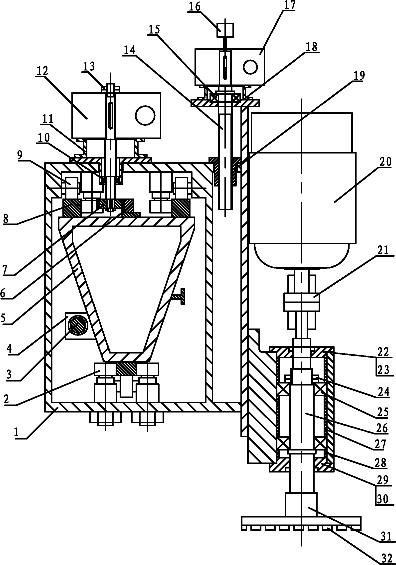
[0011] refer to figure 1 , figure 2 , image 3 As shown, the full-automatic stone milling machine is symmetrically provided with two bases 47, the base 47 is provided with an I-shaped guide rail, and a movable beam 45 and a beam drive mechanism 43 are arranged on the I-shaped guide rail. There is a tool rest 44 that can walk along the beam, and a workbench 48 is provided between the two bases 47;
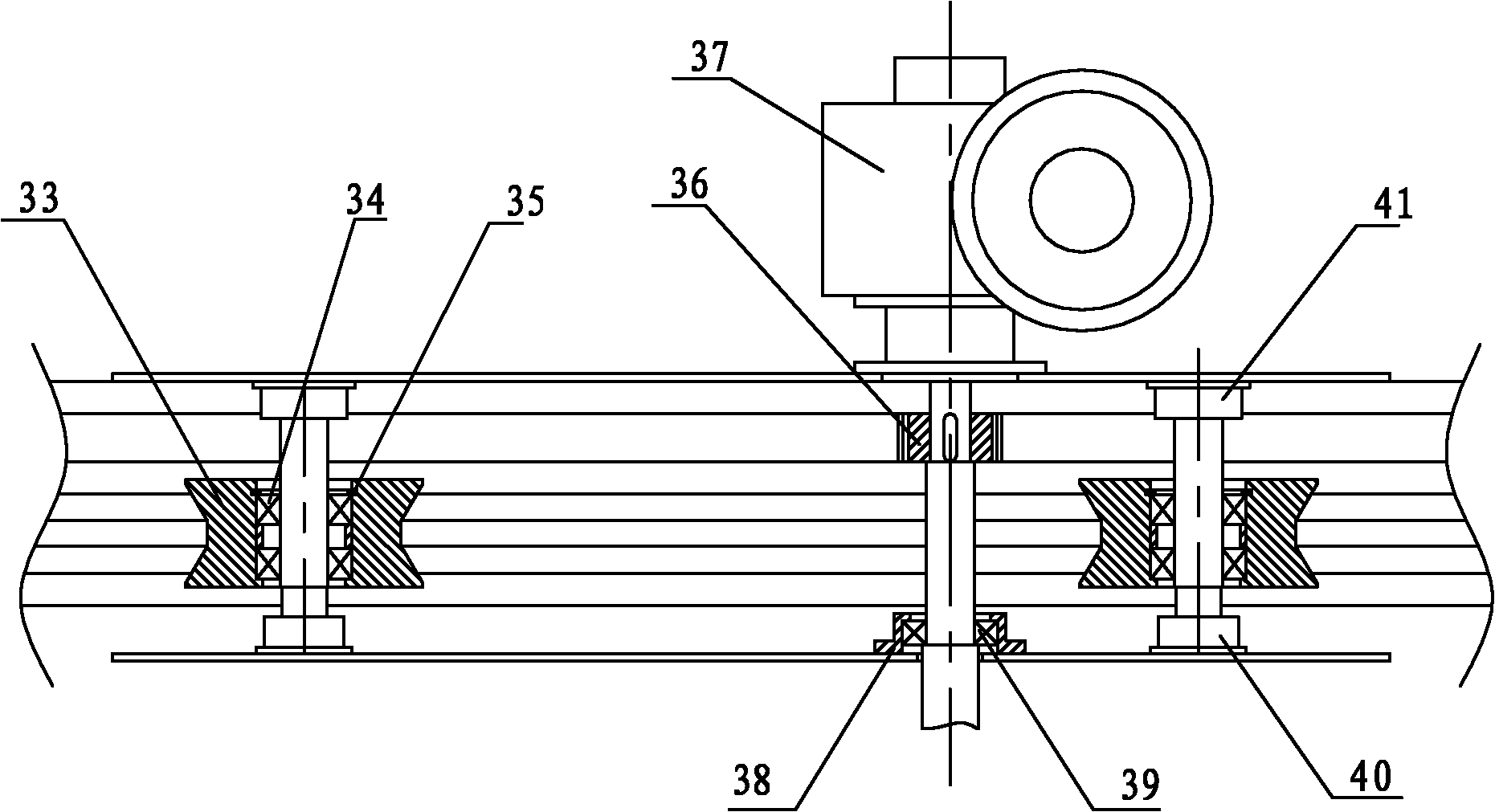
[0012] Described knife rest 44 comprises a support 1 that is installed on the described crossbeam 45, and the upper plane of crossbeam 45 is provided with two guide rails 8 symmetrically, is provided with two rollers 9 rolling on guide rail 8 correspondingly on support 1, in A rack 6 is provided on the crossbeam between the two guide rails 8, and a gear 7 meshing with the rack 6 is correspondingly provided on the bracket. The gear 7 passes through the bearing 10, and the flange 11 and a bracket 1 The reducer 12 is connected, and the other shaft end of the reducer 12 is provided with a lock nut 13; the lower part of the beam 45 is connected with the lower end of the support 1 through the vertical roller 2, and a transmission is provided on the upper part of the support 1 side. Nut 19, transmission nut 19 is provided with transmission screw rod 14, and transmission screw rod 14 is connected with a reducer 17 that is arranged on the flange 18 through bearing 15, is connected with vertical plate 49 on the base plate that flange 18 is installed, A motor 20 is arranged on the vertical plate 49, a pair of wheels 21 are arranged on the output shaft of the motor 20, an axle seat 50 is arranged on the bottom of the vertical plate 49, and skeleton oil seals 22, 30 and end caps are arranged at the two ends of the axle seat 23, 30, a pair of bearings 25 are provided in the shaft seat, and the bearings 25 are provided with a main shaft 26 through the outer lining ring 28, the inner lining ring 27 and the lock nut 24, and one end of the main shaft 26 is connected with the pair of wheels 21, The other end is connected with a cutter head 31 and a cutter head 32 .
[0013] Described beam driving mechanism 43 comprises speed reducer 37, and the drive shaft that is connected with speed reducer, is provided with gear 36 on the shaft, and drive shaft is installed on the support by bearing 38 and bearing block 39, and two pulleys are also housed on support 33, pulley 33 is installed on the support by pulley seat 41,42, bearing 34 and jump ring 35.
[0014] The invention consists of five parts: a tool spindle system, a tool holder, a beam, a base and a workbench. Driven by the motor, the tool holder can automatically run left and right on the beam, and the encoder counts to achieve precise positioning. The tool holder and the beam are connected by three-point positioning and a high-precision rack to achieve precise transmission. The tool spindle The system is driven by a screw nut, driven by a motor, and can automatically run up and down on the tool holder. The encoder is used for counting to achieve precise positioning; driven by the motor, the beam can automatically run back and forth on the base, and the encoder is used for counting. Accurate positioning is achieved; the upper part of the base is connected with a V-shaped guide rail and a high-precision rack and beam to achieve precise transmission. The lower part of the base adopts a skeleton structure, covered with iron plates, and the inner space of the base is used to make a locker, which is easy to move, beautiful and practical. The upper and lower parts of the base are connected by bolts, which are easy to disassemble and adjust; the workbench is fixed, and a layer of stone is bonded to the workbench, and the machine itself is used for milling and processing, so that the distance between the workbench and the tool surface is always kept equal.
[0015] The electrical control system of the present invention: the grinding disc is automatically lifted and lowered according to the set number; it has the functions of one-way processing and multi-directional compound processing; the functions of jogging, manual and automatic processing; different processing methods can be selected according to the characteristics of stone materials; digital fixed points are used for execution And digital quantitative automatic control; automatic alarm function, diagnosis function and help function; frequency conversion control technology. The grinding disc is automatically raised and lowered according to the set number. It has the functions of unidirectional processing and multi-directional compound processing. Inching, manual and automatic processing functions, different processing methods can be selected according to stone characteristics, digital fixed-point and digital quantitative automatic control for execution, automatic alarm function, diagnosis function and help function, frequency conversion control technology.

PUM

no PUM

Description & Claims & Application Information

We can also present the details of the Description, Claims and Application information to help users get a comprehensive understanding of the technical details of the patent, such as background art, summary of invention, brief description of drawings, description of embodiments, and other original content. On the other hand, users can also determine the specific scope of protection of the technology through the list of claims; as well as understand the changes in the life cycle of the technology with the presentation of the patent timeline. Login to view more.

Similar technology patents

Dry-type transformer

InactiveCN106504857Aeasy to moveEasy to install
Owner:JIANGSU YAWEI TRANSFORMER

Bean sprout washing equipment

InactiveCN108741139Aeasy to moveavoid jamming
Owner:WUXI SUYA FOOD CO LTD

Medical equipment transferring storage box having moisture-proof function

InactiveCN108466755Agood moisture resistanceeasy to move
Owner:ZHENGZHOU RENHONG PHARMA CO LTD

Display model for garment and leather product design

Owner:SHAANXI INST OF INT TRADE & COMMERCE

Solar energy vehicle building

InactiveCN101451398Aeasy to movecomfortable to use
Owner:SHANGHAI QIYI HIGH SCHOOL

Classification and recommendation of technical efficacy words

  • easy to move
  • Easy to adjust

Backpack medlar-picking machine

InactiveCN101473731Aeasy to movenovel structure
Owner:CHINA AGRI UNIV

Stream media broadcasting method and system

InactiveCN103763637AEasy to transfereasy to move
Owner:CHINA NSTV

Water drainage and gas production simulated experimental device

InactiveCN101806202Aeasy to move
Owner:CHINA UNIV OF PETROLEUM (EAST CHINA)

Hydraulic self-moving steel mould trolley and construction method thereof

ActiveCN103437782AFlexible removal locationeasy to move
Owner:CHINA THREE GORGES CORPORATION +1

Conference show device

InactiveCN107856443Aeasy to moveEasy and stable placement
Owner:广州小造电子商务有限公司

Method for regulating high power laser apparatus light path alignment

InactiveCN101266340Asimple equipmentEasy to adjust
Owner:SHANGHAI INST OF OPTICS & FINE MECHANICS CHINESE ACAD OF SCI

Conductive rubber and application thereof

ActiveCN102176341AGood for dust resistanceEasy to adjust
Owner:DONGGUAN MEMTECH ELECTRONICS MEMTECH ELECTRONICS PRO +2

Preparation method and application of carbon quantum dot/metal organic skeleton catalyst

ActiveCN107754861AImprove photocatalytic reactivityEasy to adjust
Owner:FUJIAN INST OF RES ON THE STRUCTURE OF MATTER CHINESE ACAD OF SCI

LED street lamp

InactiveCN101586758AEasy to adjustSimple structure
Owner:山东魏仕照明科技有限公司
Why Eureka
Try Eureka