Hydraulic control component and control circuit with same

A technology for controlling components and control loops, applied in servo motor components, fluid pressure actuating devices, servo motors, etc., can solve the problems of crawling phenomenon, abnormal impact noise, occupying time, etc., and achieve the effect of eliminating crawling phenomenon

Active Publication Date: 2011-07-27
CHANGDE ZHONGLIAN ZHONGKE HYDRAULIC
View PDF10 Cites 12 Cited by
  • Summary
  • Abstract
  • Description
  • Claims
  • Application Information

AI Technical Summary

Problems solved by technology

[0002] Small and medium tonnage truck cranes are currently on the market. In order to increase their lifting height, two-stage telescopic oil cylinders are generally used. In order to ensure telescopic control and smooth movement, the two-stage oil cylinders cannot work at the same time, but can only work alone. The mutual switching of the two-stage oil cylinders in the system relies on a special electro-hydraulic valve. On September 23, 2009, the State Intellectual Property Office published a utility model patent named "An Electro-hydraulic Valve". The number is 200820186729.2; on January 22, 2010, the State Intellectual Property Office published a patent for invention called "Electro-hydraulic memory valve", the application number is 201010110507.4, but it has the following defects: 1. When shrinking an oil cylinder , the other oil cylinder will also retract synchronously; 2. The oil in one oil cylinder is easily emptied or sucked, causing crawling phenomenon or abnormal impact during the stretching process; 3. If the sucked oil cylinder is used When the action is reversed, the hydraulic oil must first fill the empty or suction space, which will take a certain amount of time and cause the action to lag

Method used


Image

  • Hydraulic control component and control circuit with same
  • Hydraulic control component and control circuit with same
  • Hydraulic control component and control circuit with same

Examples


Embodiment Construction

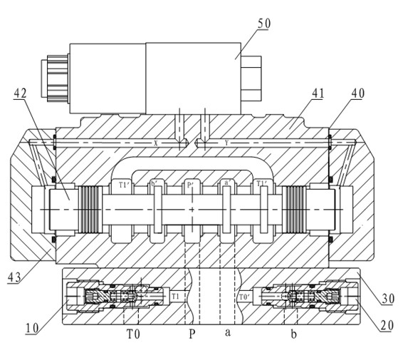
[0012] see figure 1 , taking the hydraulic control component as an electro-hydraulic valve as an example to illustrate the present invention. The electro-hydraulic valve of the present invention includes a back pressure valve 10, an oil replenishment valve 20, a base plate 30, a hydraulic control directional valve 40 and an electromagnetic directional valve 50, and the hydraulic control directional valve 40 is composed of a valve body 41, a valve stem 42 and an end cover. 43, the electromagnetic reversing valve 50 and the bottom plate 30 are respectively connected with the valve body 41 through screws, the back pressure valve 10 and the oil replenishment valve 20 are respectively inserted at both ends of the bottom plate 30, and the valve stem 42 is placed in the main hole of the valve body 41 Among them, the oil ports P, a, and b on the bottom plate 30 (that is, the oil inlet P, the first working oil port a, and the second working oil port b) are respectively connected with t...


PUM


Abstract

The invention provides a hydraulic control component and a control circuit with same. The hydraulic control component comprises a reversing valve; the reversing valve comprises an oil inlet, an oil returning hole, a first working oil hole and a second working oil hole; the hydraulic control component also comprises a back pressure valve and an oil supplementing valve, wherein the backpressure valve is connected with the oil returning hole; and the oil supplementing valve is connected with the second working oil hole. The invention also provides the control circuit applying the hydraulic control component. The hydraulic control component and the control circuit have the advantages that when an oil cylinder I expands, an oil passing chamber of the oil cylinder I is not emptily sucked, so that the crawling phenomenon is eliminated; when the oil cylinder I is shrunk, the oil cylinder I does not generate action lagging, an oil cylinder II does not reshrink along with the shrinking of the oil cylinder I; when the oil cylinders are in an idle state for a long time, oil in the oil passing chamber is not emptied, the oil passing chamber is filled with the oil all the time; when the oil cylinder II needs to shrink, the unusual sound due to impact is not generated as the oil passing chamber is not emptily sucked or discharged.

Description

technical field [0001] The invention relates to a hydraulic control assembly used in engineering machinery, in particular to a hydraulic control assembly for controlling the telescopic arm of a truck crane and a control circuit using the hydraulic control assembly. Background technique [0002] Small and medium tonnage truck cranes are currently on the market. In order to increase their lifting height, two-stage telescopic oil cylinders are generally used. In order to ensure telescopic control and smooth movement, the two-stage oil cylinders cannot work at the same time, but can only work alone. The mutual switching of the two-stage oil cylinders in the system relies on a special electro-hydraulic valve. On September 23, 2009, the State Intellectual Property Office published a utility model patent named "An Electro-hydraulic Valve". The number is 200820186729.2; on January 22, 2010, the State Intellectual Property Office published a patent for invention called "Electro-hydra...

Claims


Application Information

Patent Timeline
IPC IPC(8): F15B13/02F15B11/02
Inventor 徐尧向治平宋建清
Owner CHANGDE ZHONGLIAN ZHONGKE HYDRAULIC
Why Eureka
Try Eureka