
Automobile engine cooling water pump

A technology for automobile engines and cooling water pumps, which is applied in the direction of machines/engines, liquid fuel engines, pumps, etc. It can solve the problems of shortened life of water pumps, high maintenance frequency, and failure to achieve lubrication effects, etc., to reduce mechanical volume and improve safety Reliable, Lightweight Effects

Pending Publication Date: 2020-03-06
DAFENG HAINA MACHINERY
View PDF0 Cites 0 Cited by
  • Summary
  • Abstract
  • Description
  • Claims
  • Application Information

AI Technical Summary

Problems solved by technology

[0003] The engine cooling water pump in the prior art cannot achieve a good lubrication effect, and the maintenance frequency is high, which shortens the overall life of the water pump. In order to improve this situation, improve work efficiency, and prolong product life, the present invention proposes an automobile engine Cooling water pump

Method used


Image

  • Automobile engine cooling water pump
  • Automobile engine cooling water pump

Examples


Embodiment 1

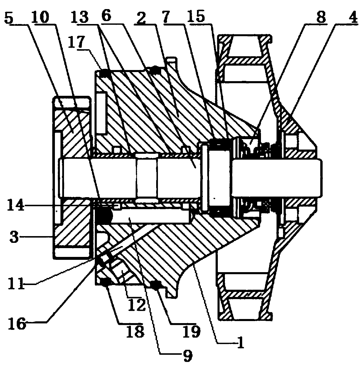
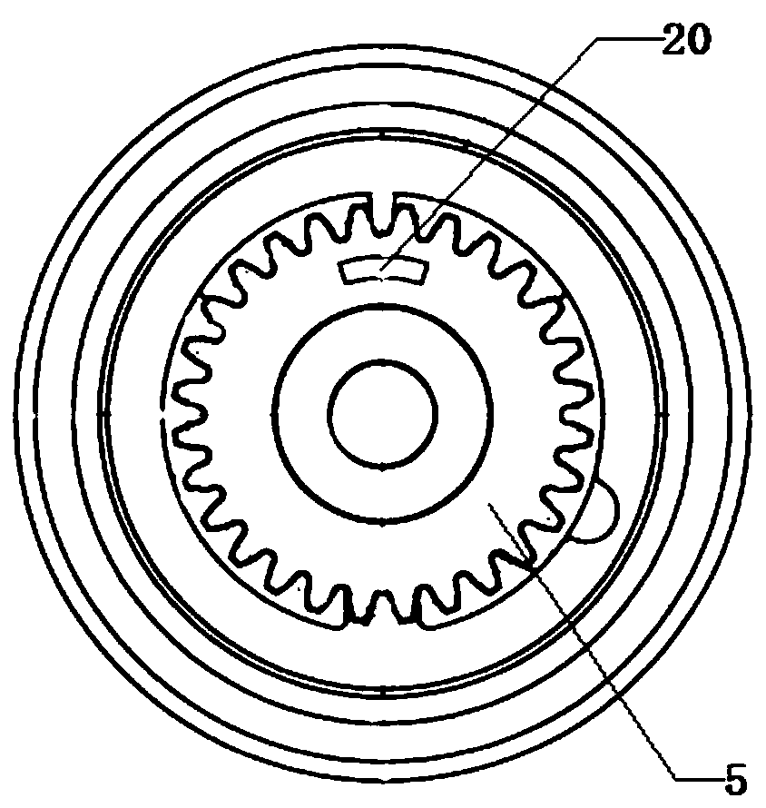
[0022] This embodiment is an automobile engine cooling water pump, including a pump casing 1, the pump casing 1 is composed of a main chamber 2 in the middle and gear chambers 3 and impeller chambers 4 on both sides of the main chamber 2, and a gear 5 is arranged in the gear chamber 3. The impeller is placed in the impeller chamber 4, and the gear chamber 3 is horizontally connected to the impeller chamber 4 with a rotating shaft 6. The rotating shaft 6 is installed throughout the pump casing 1. The shaft wall of the rotating shaft 6 in the main chamber 2 is provided with an oil seal 7, and the oil seal 7 is close to One side of the impeller chamber 4 and around the shaft wall of the rotating shaft 6 is provided with a water seal 8, and the side of the water seal 8 away from the oil seal 7 is arranged close to the inner wall of the main chamber 2; a ball groove 9 is horizontally arranged under the rotating shaft 6 and is arranged in the ball groove 9 There are steel balls 10, o...

Embodiment 2

[0025] This embodiment is an automobile engine cooling water pump, including a pump casing 1, the pump casing 1 is composed of a main chamber 2 in the middle and gear chambers 3 and impeller chambers 4 on both sides of the main chamber 2, and a gear 5 is arranged in the gear chamber 3. The impeller is placed in the impeller chamber 4, and the gear chamber 3 is horizontally connected to the impeller chamber 4 with a rotating shaft 6. The rotating shaft 6 is installed throughout the pump casing 1. The shaft wall of the rotating shaft 6 in the main chamber 2 is provided with an oil seal 7, and the oil seal 7 is close to One side of the impeller chamber 4 and around the shaft wall of the rotating shaft 6 is provided with a water seal 8, and the side of the water seal 8 away from the oil seal 7 is arranged close to the inner wall of the main chamber 2; a ball groove 9 is horizontally arranged under the rotating shaft 6 and is arranged in the ball groove 9 There are steel balls 10, o...

Embodiment 3

[0028] This embodiment is an automobile engine cooling water pump, including a pump casing 1, the pump casing 1 is composed of a main chamber 2 in the middle and gear chambers 3 and impeller chambers 4 on both sides of the main chamber 2, and a gear 5 is arranged in the gear chamber 3. The impeller is placed in the impeller chamber 4, and the gear chamber 3 is horizontally connected to the impeller chamber 4 with a rotating shaft 6. The rotating shaft 6 is installed throughout the pump casing 1. The shaft wall of the rotating shaft 6 in the main chamber 2 is provided with an oil seal 7, and the oil seal 7 is close to One side of the impeller chamber 4 and around the shaft wall of the rotating shaft 6 is provided with a water seal 8, and the side of the water seal 8 away from the oil seal 7 is arranged close to the inner wall of the main chamber 2; a ball groove 9 is horizontally arranged under the rotating shaft 6 and is arranged in the ball groove 9 There are steel balls 10, o...


PUM


Abstract

The invention discloses an automobile engine cooling water pump. The automobile engine cooling water pump comprises a pump case. The pump case is composed of a main cavity in the middle, a gear cavityand an impeller cavity, and the gear cavity and the impeller cavity are located on the two sides of the main cavity. A gear is arranged in the gear cavity. An impeller is mounted in the impeller cavity. A rotary shaft is horizontally connected from the gear cavity to the impeller cavity. The rotary shaft penetrates through the whole pump case. An oil seal is arranged on the shaft wall of the rotary shaft in the main cavity. A water seal is arranged on the side, close to the impeller cavity, of the oil seal and is arranged around the shaft wall of the rotary shaft. The side, far away from theoil seal, of the water seal is closely attached to the inner wall of the main cavity. A ball groove is horizontally formed below the rotary shaft, and a steel ball is arranged in the ball groove. Oneend of the ball groove is arranged in the position, close to the gear cavity, of a main cavity inner wall. A cooling liquid channel is arranged below the ball groove. The cooling liquid channel is connected between the main cavity inner wall and the impeller below the ball groove. The cooling liquid channel and the inner wall of the lower end of the main cavity are fixed through a supporting piece. The automobile engine cooling water pump improves the working efficiency, reduces manpower and material resources, achieves the better lubricating effect, reduces noise and is simple in structure and convenient to operate.

Description

technical field [0001] The invention relates to the technical field of water pumps, in particular to an automobile engine cooling water pump. Background technique [0002] In the cylinder block of the car engine, there are many water channels for cooling water circulation, which are connected with the water tank placed at the front of the car through water pipes to form a large water circulation system. The cooling water pump is located at the upper water outlet of the engine, and the engine passes through the pulley Drive, pump out the hot water in the water channel of the engine block, and pump the cold water in. There is a thermostat next to the water pump. When the car is just started (cold car), it is not turned on, so that the cooling water does not pass through the water tank, but only circulates in the engine. When the temperature of the engine reaches above 95 degrees, it is turned on, and the engine The hot water in the car is pumped into the water tank, and the c...

Claims


Application Information

Patent Timeline
Patent Type & Authority Applications(China)
IPC IPC(8): F04D13/02F04D29/40F04D29/10F04D29/58F04D29/046F04D29/02F04D29/06C10M167/00C10N30/06
CPCF04D13/02F04D29/406F04D29/106F04D29/586F04D29/046F04D29/026F04D29/061C10M167/00C10M2201/062C10M2201/041C10M2209/103C10M2213/02F05D2300/509
Inventor 王华生
Owner DAFENG HAINA MACHINERY
Learn More