Novel USB and eSATA connector

A connector, a new type of technology, applied in the direction of connection, device for preventing wrong connection, protective grounding/shielding device for connecting parts, etc., can solve problems such as poor durability of plugging and unplugging, tilting of USB terminals, power-on, etc., to achieve functionality and practicality Increased performance, avoid fool-proof design, and improve plug-and-plug resistance

Inactive Publication Date: 2011-07-27
赖明宏
View PDF0 Cites 3 Cited by
  • Summary
  • Abstract
  • Description
  • Claims
  • Application Information

AI Technical Summary

Problems solved by technology

[0003] Since the existing USB+eSATAI generation connector adopts the above-mentioned structure, because the eSATA terminal d1 on the lower side of the terminal receiving seat d is a data transmission terminal, unlike the USB terminal d2 on the upper side, which itself has a power terminal, it is used The eSATA terminal must be provided with additional power terminals on both sides and powered by an external power supply;
[0004] On the other hand, the recess c1 on both sides of the female base and the wings on both sides of the male head are for fool-proof design and power terminals, so most of the space on both sides of the female seat is occupied by the recess c1, so there is not enough space to simultaneously Set the power terminal and detection terminal, only one of them can be selected
In the absence of detection terminals, the static electricity on the motherboard where the existing USB+eSATA connector female seat is located cannot be released in time, so it is easy to cause harm to the equipment where the male connector is located during use, and it is also impossible for the male connector and the connector to be detected by the motherboard. Its equipment is powered on and still needs an external power supply
[0005] In addition, in the male head of the existing USB+eSATA connector, the thickness of the USB terminal receiving wall is very small, which easily causes the USB terminal to be lifted.
[0006] Therefore, the current USB+eSATA connector has a relatively complex structure and poor plug-in durability, so it has not been widely used.

Method used


Image

  • Novel USB and eSATA connector
  • Novel USB and eSATA connector
  • Novel USB and eSATA connector

Examples


Embodiment Construction

[0022] The present invention will be further described below in conjunction with specific embodiments and accompanying drawings.

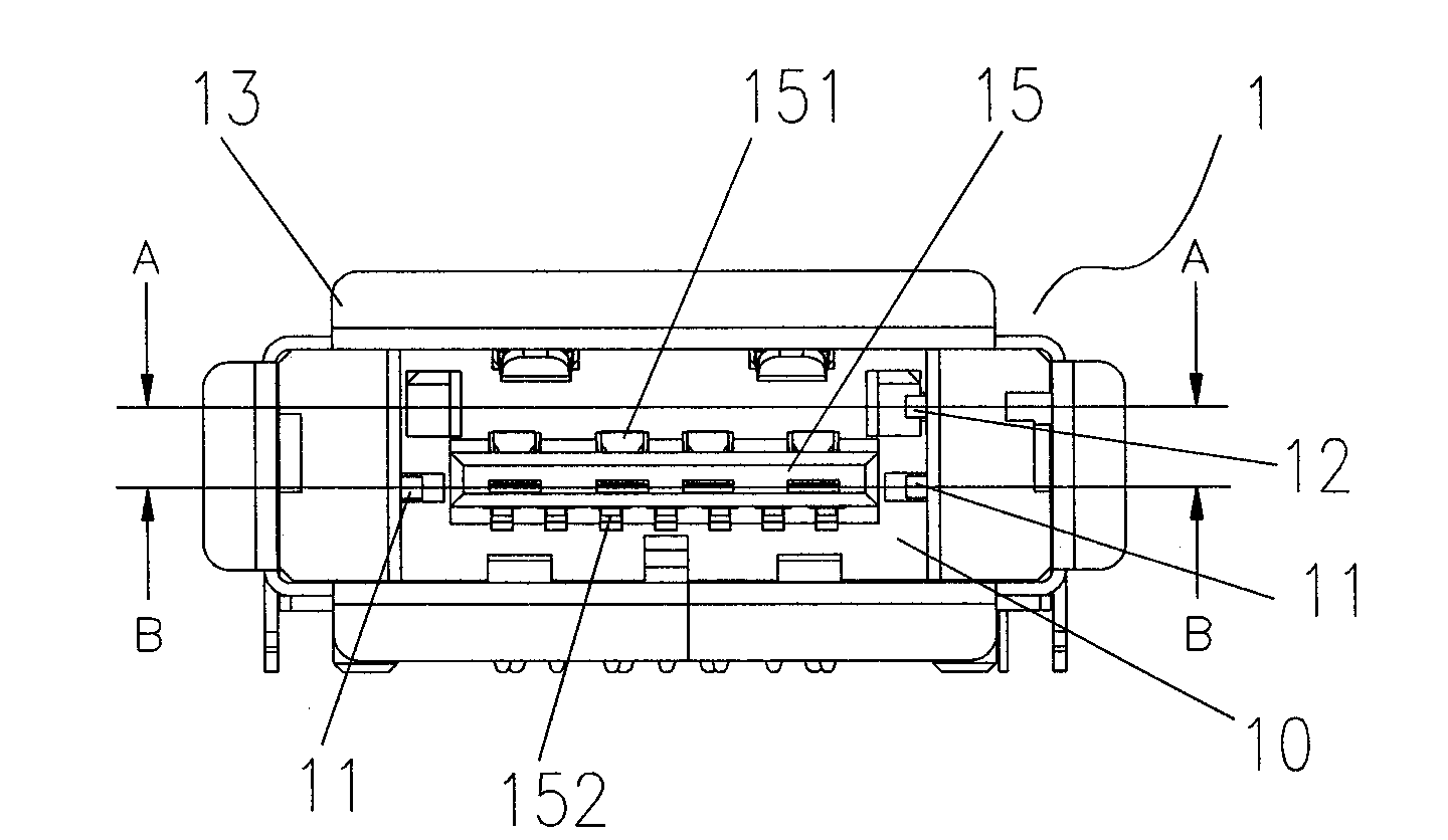
[0023] like Figure 3-7 , the new USB+eSATAII (second generation) connector described in the present invention includes a female seat 1 and a male head 2, specifically:

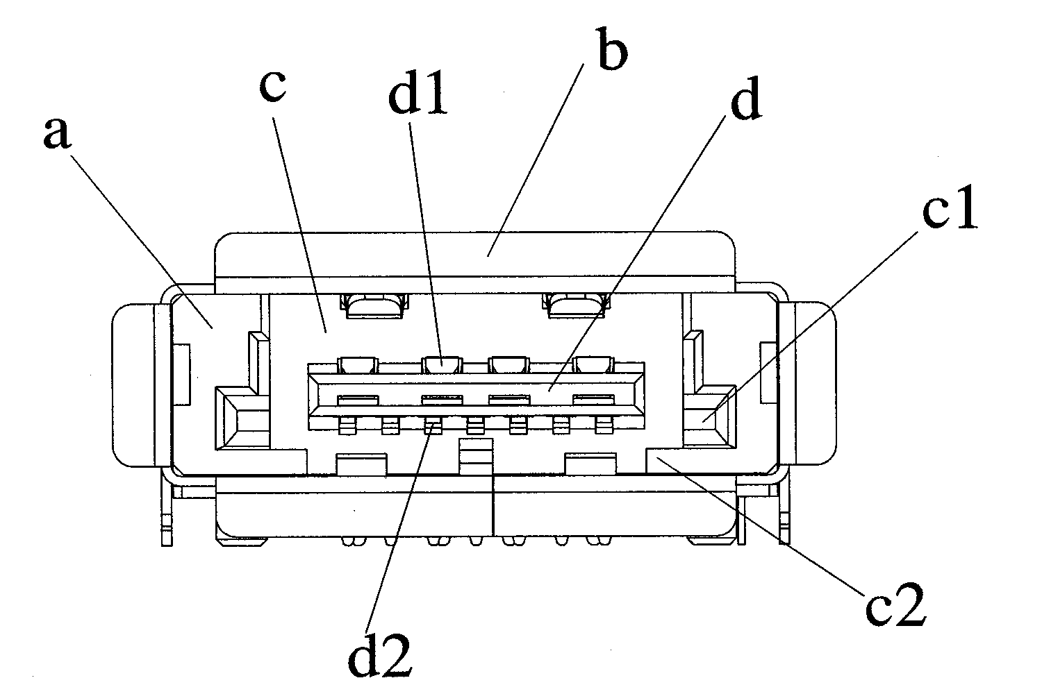
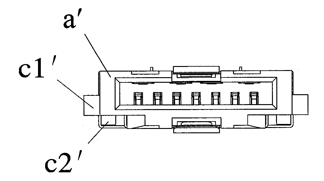
[0024] like image 3 , 4 As shown in , 5, the female seat 1 has a cavity for accommodating the male head 2, and a terminal receiving seat 15 is arranged in the cavity, and a USB terminal 151 is installed on the upper side of the terminal receiving seat 15, and an eSATA terminal 152 is installed on the lower side. The window 10 of the cavity of the female seat 1 is rectangular, combined with Image 6 , the outer frame of the corresponding male head 2 is also rectangular; protruding power terminals 11 are respectively installed on the inner sides of the two side walls of the female seat 1, combined with Figure 7 The power terminal 11 on the female seat 1 corresponds to the powe...


PUM


Abstract

The invention relates to a novel universal serial bus (USB) and eSATA II (second generation) connector. The connector comprises a female seat and a male head, wherein the female seat is provided with an accommodating cavity for accommodating the male head; the window of the accommodating cavity of the female seat is rectangular; protruding power supply terminals are respectively arranged inside the two side walls of the female seat; one of the side walls is also provided with a protruding detection terminal; the detection terminal is contacted with a copper shell out of the female seat when the male head is combined with the female seat; correspondingly, the frame of the male head is also rectangular; concave surfaces and power supply terminals are respectively arranged outside the two side walls of the male head; and the power supply terminals are contacted with the power supply terminals of the female seat when the male head is combined with the female seat. The novel USB and eSATA connector solves an eSATA terminal power supply problem and a mainboard discharge problem; the plug and pull resistance of the connector is greatly improved; therefore, a way is paved for the extensive use of the USB and eSATA II (second generation) connector.

Description

Technical field: [0001] The invention relates to the technical field of electronic connector components, in particular to a novel USB and eSATA connector. Background technique: [0002] In the design and manufacture of electronic connectors, a fool-proof design is usually used to prevent adverse consequences caused by misconnection. The existing USB+eSATA connector (or called USB+eSATAI (first generation)), its female seat structure is as follows: figure 1 As shown, it mainly includes a plastic body a, a peripheral copper shell b, a cavity c, and an internal terminal receiving seat d, etc. The two sides of the window of the cavity c are provided with a concave part c1 in a stepped shape, and two corners are also set Protruding step body c2 along the length direction; such as figure 2 As shown, the two sides of the corresponding male head a' are provided with protruding wings c1' corresponding to the concave part c1, and the two corners are provided with cutting parts c2' ...

Claims


Application Information

Patent Timeline
Patent Type & Authority Applications(China)
IPC IPC(8): H01R27/00H01R12/70H01R13/46H01R13/02H01R13/64H01R13/648
Inventor 赖明宏
Owner 赖明宏
Why Eureka
Try Eureka