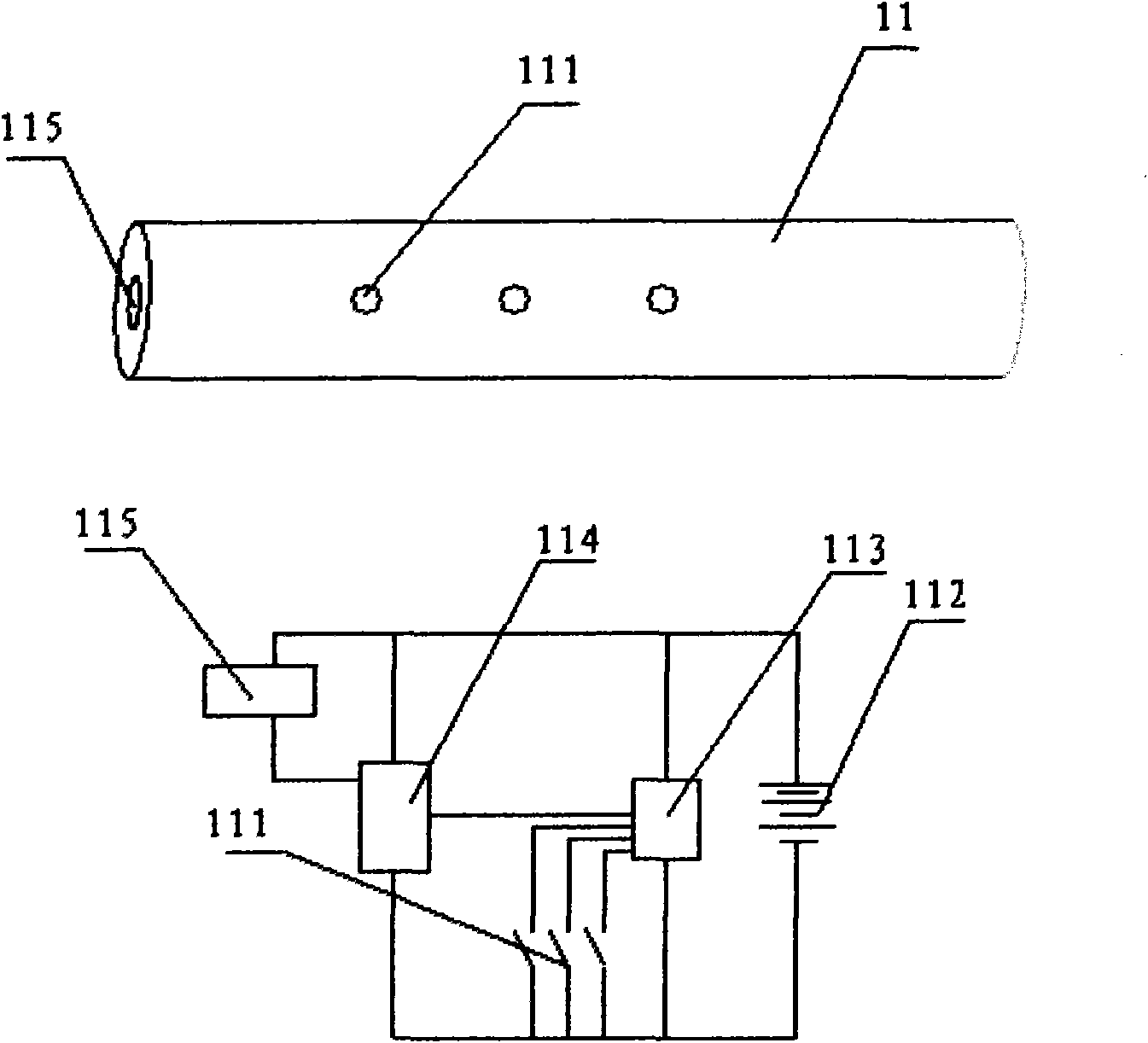
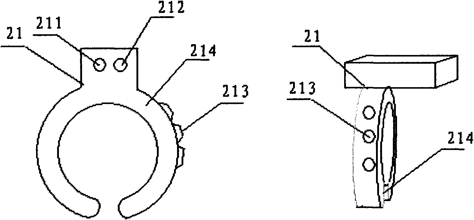
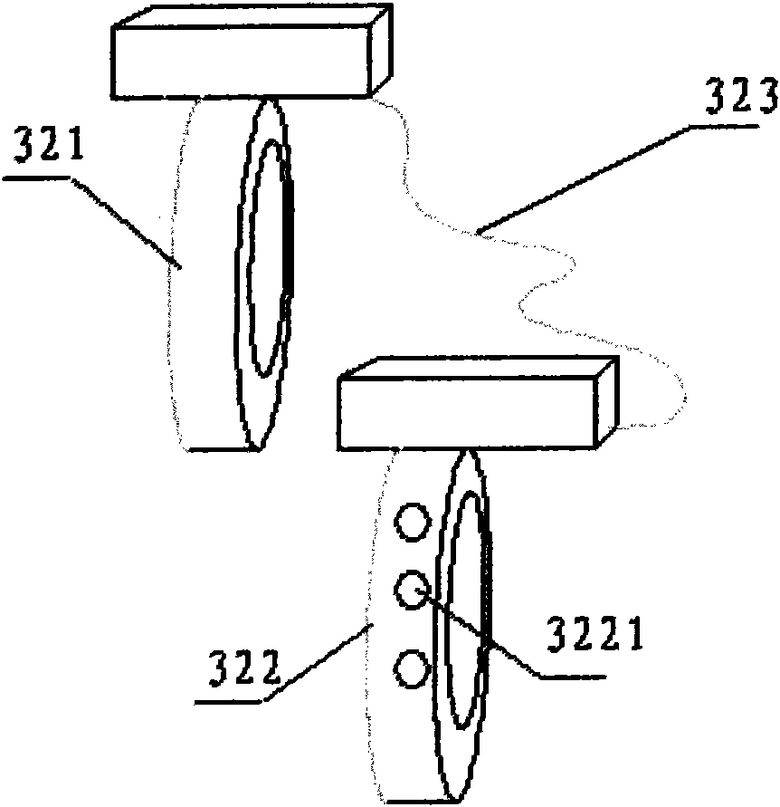
Laser remote control receiving system and transmitter
A technology of remote control receiving and laser, applied in the field of laser remote control system, can solve the problems of increasing the photosensitive area, affecting the size and appearance of electrical appliances, and being inapplicable
- Summary
- Abstract
- Description
- Claims
- Application Information
AI Technical Summary
Problems solved by technology
Method used
Image
Examples
Embodiment 1
[0106] There are many kinds of remote control electric lights now, and the remote control electric lights include remote controllers, signal receivers, and electric lights.
[0107] The laser remote control signal transmitter is used as a remote control, and the laser remote control receiving system is used as a signal receiver. The structure of the astigmatism plate part of the laser remote control receiving system is as follows: Figure 4 .
[0108] The diffuser plate 41 is a fan-shaped flat box made of translucent plastic. The upper layer of the diffuser plate 41 mainly scatters the optical signal, and the lower layer diffusely reflects the optical signal.
[0109] The phototransistor 42 is located at the top of the fan-shaped diffuser 41 and at the back of the side of the diffuser 41 that is irradiated by the laser light. Since light signals are everywhere in the diffuser plate 41 after scattering and diffuse reflection, the direction of the photosensitive surface of th...
Embodiment 2
[0122] refer to Figure 5 , The laser remote control receiving system includes four filter channels 521, 522, 523, 524 and photosensitive triodes and astigmatism plates installed inside. The diffuser plate 525 uses a TV screen.
[0123] Each filter channel has the same basic structure, take the filter channel 521 as an example, refer to Figure 6 To illustrate, the light transmission port of the filter channel 521 is equipped with a red glass 5212 to prevent dust from entering and to filter light, and a phototransistor with a photosensitive surface facing the red glass 5212 is installed in the filter channel 521 .
[0124] refer to Figure 5 , the filter channels 521, 522, 523, 524 are installed in the parts where the TV casing 526 is in contact with the TV screen 525, and are respectively located in the middle of the top, bottom, left and right of the TV screen, and the photosensitive surface faces the diffuser plate 525 .
[0125] The signal processing device is connected ...
Embodiment 3
[0148] refer to Figure 7 , the projector system has a projector 61 and a screen 62, and the laser remote control receiving system uses the screen 62 of the projector system as a diffuser.
[0149] refer to Figure 8 , the two optical components 612 and 613 of the laser remote control receiving system are installed on the projector 61, and are respectively located on the left and right of the lens 611.
[0150] The working principle of the laser remote control receiving system applied to the projector system is the same as that of the laser remote control receiving system applied to the TV set. The screen is divided into two parts by calculating the signal difference, and the action of the laser signal on the screen is used as the remote control signal information.
[0151] The laser remote control signal transmitter has at least two buttons, one button controls the laser to send out a non-controlled laser signal, which only serves as an indicator; one button controls the la...
PUM
 Abstract
Description
Claims
Application Information
 - R&D
- Intellectual Property
- Life Sciences
- Materials
- Tech Scout
- Unparalleled Data Quality
- Higher Quality Content
- 60% Fewer Hallucinations
Browse by: Latest US Patents, China's latest patents, Technical Efficacy Thesaurus, Application Domain, Technology Topic, Popular Technical Reports.
© 2025 PatSnap. All rights reserved.Legal|Privacy policy|Modern Slavery Act Transparency Statement|Sitemap|About US| Contact US: help@patsnap.com


