
Underwater object lifting device

A hoisting and hoisting technology, which is used in underwater operation equipment, transportation and packaging, and vessel salvage, etc., can solve problems such as operation failure, hoisting failure, and being easily affected by sea conditions.

Inactive Publication Date: 2011-08-03
中国船舶重工集团公司第七〇二研究所
View PDF4 Cites 28 Cited by
  • Summary
  • Abstract
  • Description
  • Claims
  • Application Information

AI Technical Summary

Problems solved by technology

[0004] A. The control and retraction devices are all located on the deck of the working mother ship, which is easily affected by the sea conditions. Even in the sea conditions that can be operated, when the wind and waves are strong, the hoisting system and the hull will sway with the wind and waves, which often leads to lifting operations. failure, the work efficiency is very low
[0005] B. The function of the conventional lifting mechanism cannot meet the requirements for lifting objects on the seabed
The sampling device is only suitable for seabed mineral sampling, and the conventional lifting device requires the cooperation of personnel and operational ROVs to complete the lifting task. It is difficult to coordinate between different groups during the operation, and often the operation fails due to coordination errors, which affects work efficiency
[0006] C. Since there is no propulsion system in the hook part, it is impossible to search for target objects through the hook, so the positioning requirements for the surface mother ship are relatively high
[0007] D. The hoisting operation is carried out on the sea surface, which is easy to be monitored and is not conducive to concealed operations

Method used


Image

  • Underwater object lifting device
  • Underwater object lifting device
  • Underwater object lifting device

Examples


Embodiment Construction

[0018] The specific implementation manners of the present invention will be further described in detail below in conjunction with the accompanying drawings.

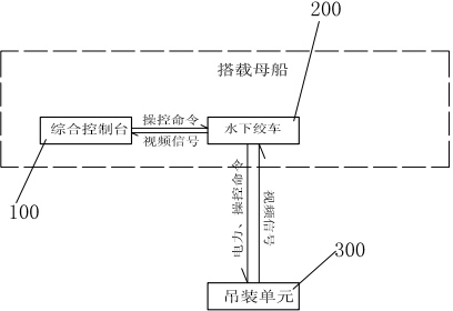
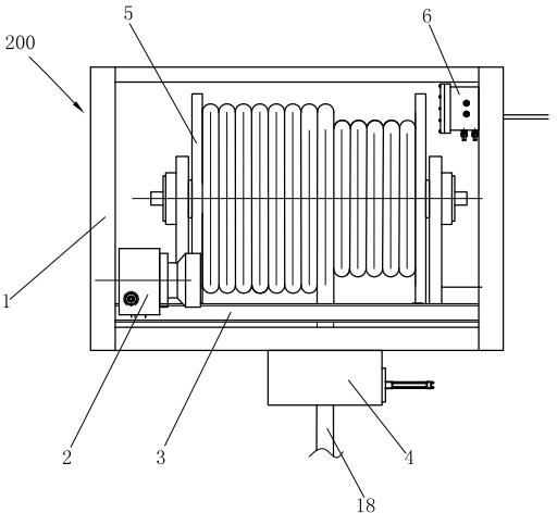
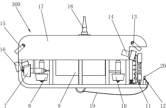
[0019] Such as figure 1 , 2 , 3, the present invention comprises integrated console 100, underwater winch 200 and hoisting unit 300, integrated console 100 and underwater winch 200 are connected by watertight cables, between underwater winch 200 and hoisting unit 300 through armored cables 18, the armored cable 18 can bear the weight of the hoisting unit 300 and the lifting object, and at the same time provide power support for the hoisting unit 300 and transmit the control signal sent by the integrated console 100. In the present invention, a submarine or an underwater mobile workstation is used as a mother ship, and the integrated control console 100 is arranged in the dry working cabin of the mother ship. The integrated console 100 includes a winch status monitoring module, a hoisting unit image display module, a win...


PUM


Abstract

The invention relates to an underwater object lifting device. The invention is characterized in that the device comprises an integrated control console, an underwater winch and a lifting unit, wherein the integrated control console is connected with the underwater winch by a watertight cable; the underwater winch is connected with the lifting unit by an armored cable; the lifting unit comprises alifting main body; a central control device is arranged at the middle part of the lifting main body; the stem part and the stern part of the lifting main body are respectively provided with an image pickup device and a lighting device; both sides of the stern part of the lifting main body are provided with horizontal thrusters; a lifting hook is connected with the center of the bottom of the lifting main body by a steel cable; and the stem part of the lifting main body is provided with a manipulator and a lifting-hook hanging post. A submarine or an underwater mobile work station is taken as a carrying mother ship of the underwater lifting device; the integrated control console controls the underwater winch and the lifting unit to release and recycle target objects underwater; the underwater lifting device reduces the influence of stormy waves on lifting operation, improves the operation efficiency and is suitable for underwater hidden operation; in addition, the lifting unit is provided with the horizontal thrusters and vertical thrusters and has lower requirements on positioning the mother ship.

Description

technical field [0001] The invention relates to an underwater object hanging device, which is used for deploying and recovering target objects in water. Background technique [0002] Underwater lifting technology is the research frontier and important key technology of today's underwater operation tools, and has important economic and military value. It can lift equipment that needs urgent maintenance from the seabed, support the construction of subsea oil fields, participate in marine archaeology, investigate deep-sea sunken ships, Salvage of precious cultural relics, etc. [0003] Offshore hanging objects are often used in underwater mine sample salvage. For example, a surface ship is used to drag a trawling device to take underwater mine samples, and a gravity sampler is usually used to grab underwater sediments by using the kinetic energy of the sampler. In subsea salvage and subsea oil field construction, it is carried out through the winch installed on the deck equipp...

Claims


Application Information

Patent Timeline
IPC IPC(8): B63C11/52B63C7/26
Inventor 马利斌刘涛胡勇马岭
Owner 中国船舶重工集团公司第七〇二研究所
Learn More