Structure for improving cooling efficiency of gas film of discrete hole

A film cooling, discrete hole technology, applied in the cooling of the engine, the cooling of the turbine/propulsion device, the supporting element of the blade, etc., can solve the problems of low cooling efficiency, decreased cooling efficiency, etc., and achieve a simple and convex structure. Small size, great effect

Active Publication Date: 2011-08-03
INST OF ENGINEERING THERMOPHYSICS - CHINESE ACAD OF SCI
View PDF6 Cites 34 Cited by
  • Summary
  • Abstract
  • Description
  • Claims
  • Application Information

AI Technical Summary

Problems solved by technology

The air film cooling in the form of discrete holes usually has a low cooling efficiency between holes (lateral direction), and when the hole spacing is large, the cooling efficiency between holes drops rapidly

Method used


Image

  • Structure for improving cooling efficiency of gas film of discrete hole
  • Structure for improving cooling efficiency of gas film of discrete hole
  • Structure for improving cooling efficiency of gas film of discrete hole

Examples


Embodiment Construction

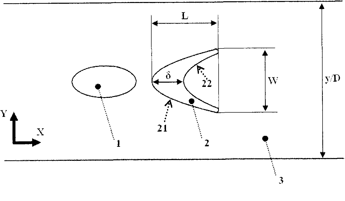
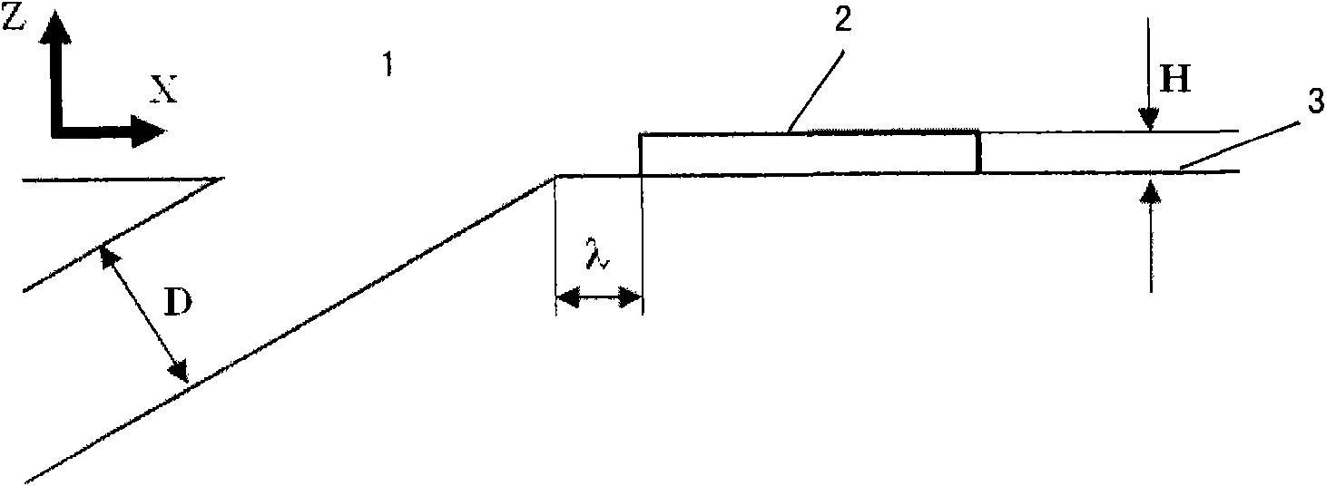
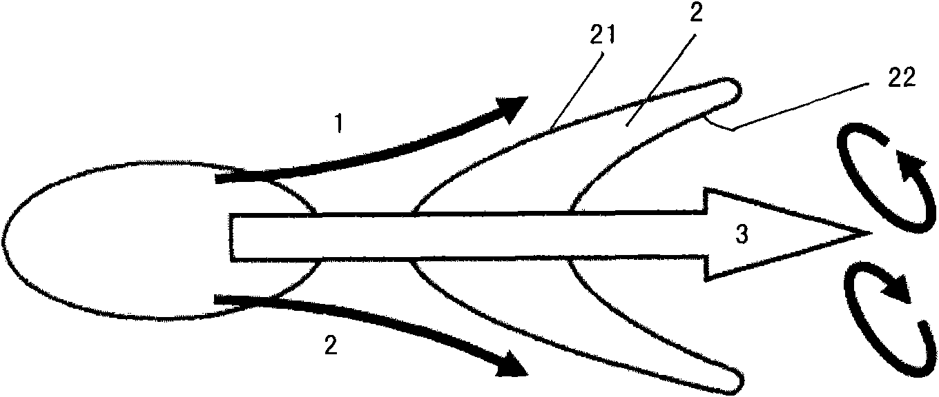
[0034] As shown in FIG. 1 , it is a schematic structural diagram of improving the efficiency of film cooling of discrete holes according to the present invention, wherein, film holes 1 , protrusions 2 , and surfaces 3 . It is defined by the structural parameters of the crescent-shaped protrusion 2 downstream of the air film hole 1 shown in FIG. 1 . The length, width and height of the protrusion 2 are represented by L, W and H respectively. The diameter of air film hole 1 is represented by D. Several main flow directions are shown by coordinates X, Y, and Z respectively, where X is the flow direction, Y is the transverse direction, and Z is the radial direction. The flow distance between the protrusion 2 and the air outlet side of the air film hole 1 is represented by λ. The maximum thickness of the protrusion 2 is indicated by δ. In addition, the profile line of the protrusion 2 along the upstream side is defined as the intake side line 21 of the protrusion 2 , and the prof...


PUM


Abstract

The invention discloses a structure for improving the cooling efficiency of a gas film of a discrete hole, which relates to a gas turbine technology and is used for cooling a turbine blade for a gas turbine and the gas film of the wall surface of a combustion chamber. In the structure, a bulge is placed adjacent to the rear part of the outlet of a gas film cooling hole, the bulge is bilaterally symmetrical by taking a central line of the gas film hole as a symmetric axis, the width of the bulge is about two times the diameter of the gas film hole, the ratio of the length to the width of the bulge is about 1, and the height of the bulge is about one fourth the diameter of the gas film hole. The bulge has the following three functions that: 1, cooling air is transversely extended, and the transverse coverage area of an atmosphere area can be increased; 2, the rotation direction of a cooling air kidney-shaped vortex pair at the outlet of the conventional gas film can be changed, and the cooling air can be adhered to a wall surface conveniently; and 3, the low bulge height guarantees that most of gas film cooling air is adhered to the wall surface again after axially flowing around the bulge and the cooling air is provided for the newly produced vortex pair. The bulge of the structure has a small size and low height, so that the additional flow loss is very low. The structure is suitable for cooling all gas films in a discrete hole form.

Description

technical field [0001] The invention relates to the technical field of gas turbines, and is a new structure of discrete hole film cooling, which can improve the gas film cooling efficiency of gas turbine blades and walls of combustion chambers, and is suitable for all types of discrete hole film cooling. Background technique [0002] As an efficient cooling technology, discrete hole film cooling is widely used in the cooling of gas turbine blades and combustion chamber walls. The basic principle is that the cooling air flows out through the air film holes, so that the cooling air covers the surface of the blade, so as to achieve the purpose of isolating the main flow of heat and the surface of the metal blade. The air film cooling in the form of discrete holes usually has a low cooling efficiency between the holes (transverse direction), and the cooling efficiency between the holes drops rapidly when the hole spacing is large. For discrete hole film cooling, one of the core...

Claims


Application Information

Patent Timeline
Patent Type & Authority Applications(China)
IPC IPC(8): F02C7/18
CPCF01D5/186
Inventor 安柏涛刘建军
Owner INST OF ENGINEERING THERMOPHYSICS - CHINESE ACAD OF SCI
Why Eureka
Try Eureka