Riser stress measuring device and measuring method

A technology of stress measurement and measurement device, which is applied in the direction of measuring force by measuring the change of optical properties of materials when they are stressed, and can solve the problems of high sensitivity, easy damage to the anti-corrosion coating of the riser, and reduced accuracy of the measurement results.

Inactive Publication Date: 2011-08-03
CHINA NAT OFFSHORE OIL CORP +2
View PDF9 Cites 31 Cited by
  • Summary
  • Abstract
  • Description
  • Claims
  • Application Information

AI Technical Summary

Problems solved by technology

Among them, the binding method usually uses a displacement sensor, and the stress data is obtained by using the displacement signal collected by the displacement sensor. The collected displacement signal is an electrical signal, so electromagnetic shielding must be used for processing, and the operation is cumbersome and complicated.
The bonding method uses a polymer-coated optical fiber sensor, and the sensing method is an interference ceremony. However, the bonding method is not only easy to damage the anti-corrosion coating of the riser, but also the interference method is highly sensitive to the external environment, which makes the measurement results decreased accuracy

Method used


Image

  • Riser stress measuring device and measuring method
  • Riser stress measuring device and measuring method
  • Riser stress measuring device and measuring method

Examples


Embodiment 1

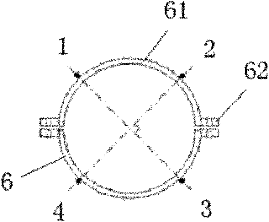
[0035] Such as image 3 , Figure 4 As shown, the present embodiment includes a cable tie 6, and the cable tie 6 includes two semi-circular rings 61 symmetrically arranged, and a connection plate 62 is respectively provided at the joint at both ends of each semi-circular ring 61, and the two semi-circular rings 61 correspond to The two pairs of connection plates 62 are fixedly connected into one body by bolts. The combined inner diameter of the two semicircular rings 61 is slightly smaller than the outer diameter of the riser, so as to ensure that the combined inner diameter and the outer diameter of the riser 5 can fit together closely. The four sensors 1 , 2 , 3 , 4 are respectively fixed on the cable tie 6 at 45° to their adjacent connecting pads 62 , and are located on the same circumference.

Embodiment 2

[0037] Such as Figure 5 , Image 6 As shown, this embodiment includes two cable ties 7 arranged in parallel, and each cable tie 7 includes four quarter rings 71, and the joints at both ends of each quarter ring 71 are respectively provided with a connection The discs 72 and the corresponding four pairs of connecting discs 72 on the four quarter rings 71 are fixedly connected into one body by bolts. The combined inner diameter of the four quarter rings 71 on each cable tie 7 is slightly smaller than the outer diameter of the riser 5 to ensure that the combined inner diameter and the outer diameter of the riser 5 can fit together tightly . A T-shaped beam 73 is oppositely arranged at the midpoint of every two quarter rings 71 arranged in parallel, and a sensor 1, 2, 3, 4 (sensor 4) is respectively arranged between four pairs of opposite T-shaped beams 73 bottom ends. Not visible in the figure), the four sensors 1, 2, 3, 4 are located on the same circumference.

[0038] In t...


PUM


Abstract

The invention relates to a riser stress measuring device and a measuring method. Four fiber Bragg grating stress sensors are arranged around the riser, namely the four fiber Bragg grating stress sensors are arranged around the axial direction of the riser 5, and the four sensors are positioned in the same circle on the outer wall of the riser at an interval of 90 DEG. When an external force is applied onto the riser, the four sensors arranged on the outer side of the riser are stretched and bent. In the invention, the circumferential and bending combined stress of the riser can be measured and calculated by the sensors. The device has a simple structure, low external environment sensitivity and high measurement structure accuracy, and can be widely used in measurement of stress of various risers.

Description

technical field [0001] The invention relates to a riser stress measuring device and a measuring method, in particular to a riser stress measuring device and a measuring method based on an optical fiber grating strain sensor. Background technique [0002] With the continuous development of offshore oil into the deep water field, the riser lengthens with the increase of water depth. Whether its strength and stability can meet the requirements of deep water drilling has become the main consideration of deep water drilling. Under deep water conditions, the stress state of the riser string is very complex and harsh. Many floating drilling ships or platforms have interrupted drilling operations due to the inability of the riser to adapt to and withstand the huge comprehensive external force, and even failed to resume drilling, resulting in Accidents such as drilling failures have caused huge losses to offshore drilling projects. Therefore, obtaining real-time and reliable monitor...

Claims


Application Information

Patent Timeline
Patent Type & Authority Applications(China)
IPC IPC(8): G01L1/24
Inventor 周建良杨德兴蒋世全王海燕许亮斌申晓红何轲邓欣姜亚军王骏秦川
Owner CHINA NAT OFFSHORE OIL CORP
Why Eureka
Try Eureka