
V-shaped slot rotor of self-starting permanent magnet synchronous motor

A technology of permanent magnet synchronous motor and V-groove, which is applied in the direction of synchronous machine parts, magnetic circuit rotating parts, magnetic circuit shape/style/structure, etc., and can solve the problem of increasing eddy current loss of permanent magnets, squirrel cages and iron cores, Problems such as poor mechanical stress of the rotor silicon steel sheet and irreversible loss of magnetism of the permanent magnet can avoid local loss of magnetism, optimize the magnetic circuit, and improve efficiency

Inactive Publication Date: 2011-08-03
ZHEJIANG UNIV
View PDF4 Cites 8 Cited by
  • Summary
  • Abstract
  • Description
  • Claims
  • Application Information

AI Technical Summary

Problems solved by technology

[0004] 1. During the starting process, the internal magnetic circuit of the rotor will be severely distorted, which may easily cause irreversible loss of magnetism locally
[0005] 2. The magnetic density in the rotor changes drastically, which increases the eddy current loss in the permanent magnet, squirrel cage and iron core, and affects the performance of the motor
[0006] 3. The mechanical stress of the rotor silicon steel sheet is relatively poor, and the radial tension of the rotor is only provided by the magnetic isolation bridge between the permanent magnet and the squirrel cage bars

Method used


Image

  • V-shaped slot rotor of self-starting permanent magnet synchronous motor
  • V-shaped slot rotor of self-starting permanent magnet synchronous motor
  • V-shaped slot rotor of self-starting permanent magnet synchronous motor

Examples


Embodiment Construction

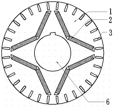
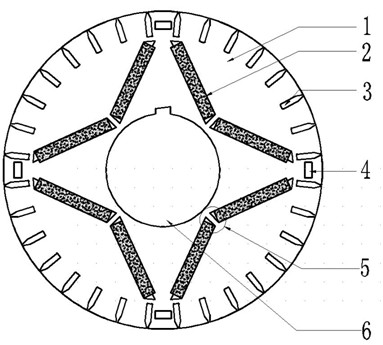
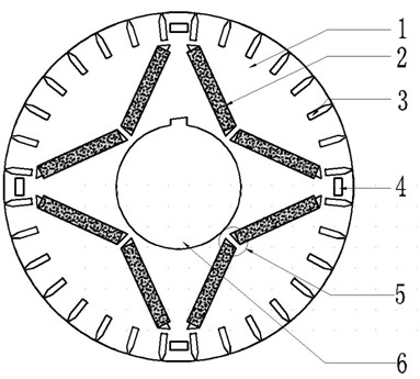
[0028] refer to figure 2 The self-starting permanent magnet synchronous motor V-groove rotor includes iron core 1, permanent magnet 2, squirrel cage guide bar 3 and shaft 6. The iron core has grooves arranged in a V shape, and every two permanent magnets placed in the V-shaped groove constitute One magnetic pole, the illustrated example has 4 magnetic poles, the bottom of each V-shaped groove is separated, forming a magnetic bridge of two permanent magnets in the V-shaped groove, and two squirrel cage guide bars corresponding to the top of the adjacent V-shaped groove 3 Axial air grooves 4 are arranged between them.

[0029] The V-groove rotor of the self-starting permanent magnet synchronous motor of the present invention can also only use the bottom of each V-groove to separate each other to form a magnetic bridge of two permanent magnets in the V-groove. Or only the axial air grooves are arranged between the two squirrel cage guide bars corresponding to the tops of the ad...


PUM


Abstract

The invention discloses a V-shaped slot rotor of a self-starting permanent magnet synchronous motor, comprising an iron core, permanent magnets, squirrel-cage conducting bars and a shaft, wherein the iron core is provided with slots which are arranged as a V shape, every two permanent magnets arranged in the V-shaped slot form a magnetic pole, bottoms of all the V-shaped slots are separated to form magnetic bridges of the two permanent magnets in the V-shaped slots, and an axial air slot is arranged between every two squirrel-cage conducting bars corresponding to the tops of the corresponding adjacent V-shaped slots; or only are the bottoms of all the V-shaped slots separated to form magnetic bridges of the two permanent magnets in the V-shaped slots; or only is the axial air slot arranged between every two squirrel-cage conducting bars corresponding to the tops of the corresponding adjacent V-shaped slots. Compared with the V-shaped slot rotor used in China and abroad, the V-shaped slot rotor disclosed by the invention avoids the phenomenon of local demagnetizing of the permanent magnets in the starting process, simultaneously reduces the eddy-current loss inside the rotor in the steady-state running process and has a certain effect on improving the reliability and the steady-state performance of the self-starting permanent magnet synchronous motor.

Description

technical field [0001] The invention relates to a rotor of a self-starting permanent magnet synchronous motor. Background technique [0002] In recent years, self-starting permanent magnet synchronous motors have attracted more and more attention. Compared with asynchronous motors, they have high operational stability, higher efficiency and power factor than asynchronous motors of the same power level, and wide economical operating range. They are widely used in many industrial applications. It is expected to replace asynchronous motors, but the reliability of permanent magnets has been an important factor hindering the widespread application of such motors. As far as the motor body structure is concerned, the existing self-starting permanent magnet synchronous motor rotor structure can be divided into parallel, series and hybrid structures according to the placement of permanent magnets. The V-shaped groove structure is a kind of series structure. The existing V-shaped gro...

Claims


Application Information

Patent Timeline
Patent Type & Authority Applications(China)
IPC IPC(8): H02K21/02H02K1/27
Inventor 沈建新李鹏杨光张江
Owner ZHEJIANG UNIV
Learn More