Folding bicycle parking frame

A technology for bicycles and parking racks, applied in the directions of bicycle brackets, bicycle accessories, transportation and packaging, can solve the problems of high cost, inability to provide folding, large use space, etc. Effect

Inactive Publication Date: 2011-08-10
TOPEAK
View PDF1 Cites 9 Cited by
  • Summary
  • Abstract
  • Description
  • Claims
  • Application Information

AI Technical Summary

Problems solved by technology

[0003] However, this fixed bicycle rack that cannot be folded has many shortcomings during transportation and use.
In terms of transportation, when such a large-volume device is sealed, there are too many gaps in the packaging box. In order to prevent the packaging box from being dented when it collides, it is necessary to fill the gaps in the packaging box with protective partitions or Styrofoam , which increases the material cost of packaging and the labor cost of filling
In addition, due to the large volume of the packaging box, the number of packaging boxes that can be accommodated in the container is reduced, and the number of containers must be increased, thereby increasing the cost of transportation
In view of its high cost, such a design must be reflected in the selling price, and products with a high unit price cannot win the favor of ordinary consumers, so the design of this fixed bicycle rack does not meet the requirements of energy saving and carbon reduction at all.
Furthermore, when consumers purchase a fixed bicycle rack, this design that cannot be folded must take up a large space for use. When the fixed bicycle rack is not in use, because it is bulky and cannot be folded, consumers have The trouble of not being able to collect
[0004] The aforementioned patents have the disadvantages of high cost, bulky size, high price, and failure to meet the expectations of consumers. The inventor tried his best to find a solution in view of the deficiencies of the prior art

Method used


Image

  • Folding bicycle parking frame
  • Folding bicycle parking frame
  • Folding bicycle parking frame

Examples


Embodiment Construction

[0053] Regarding the technology, means and effects used in the present invention, a preferred embodiment is given and described in detail below with drawings, which are for illustration purposes only, and are not limited by this structure in the patent application.

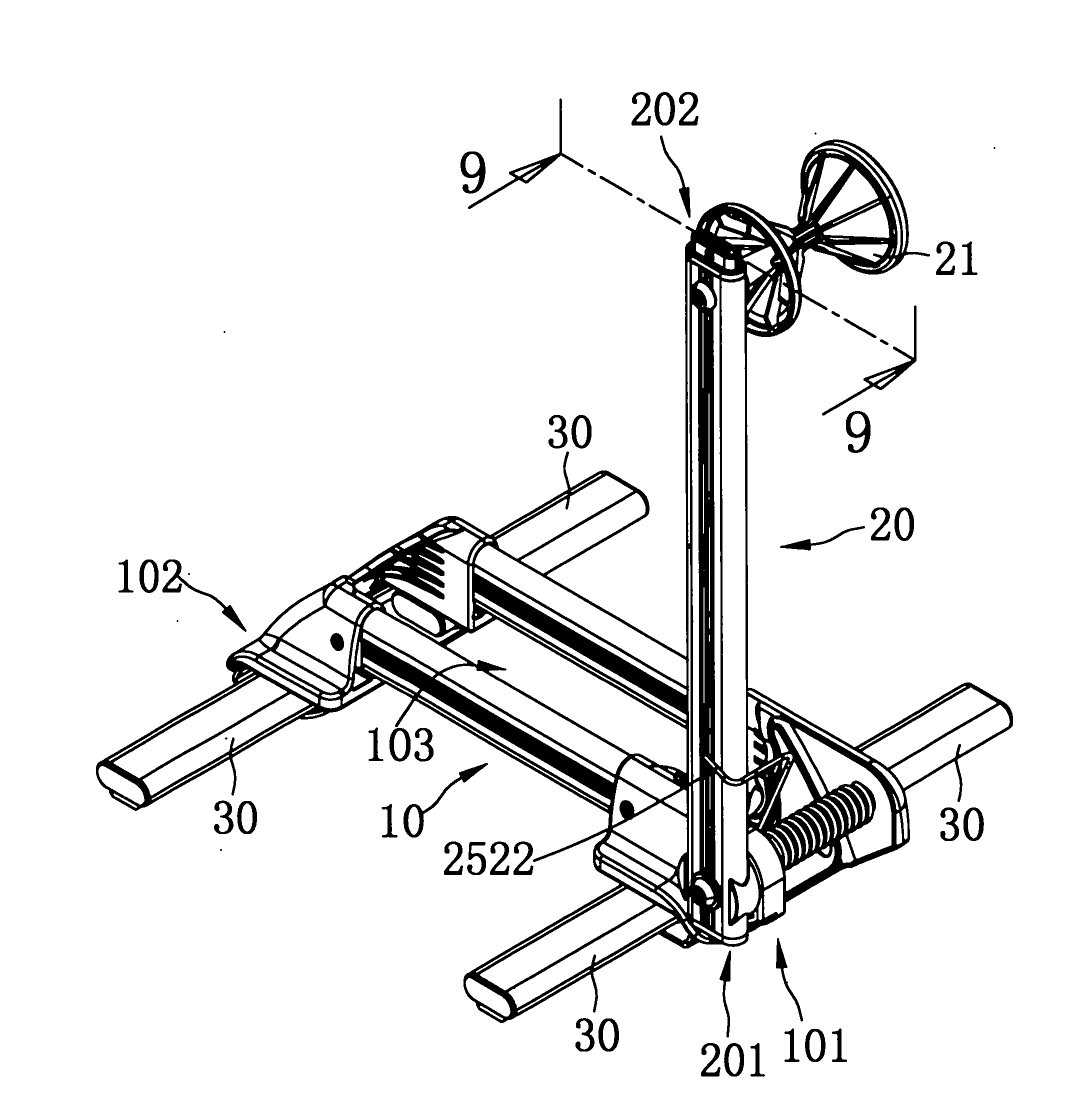
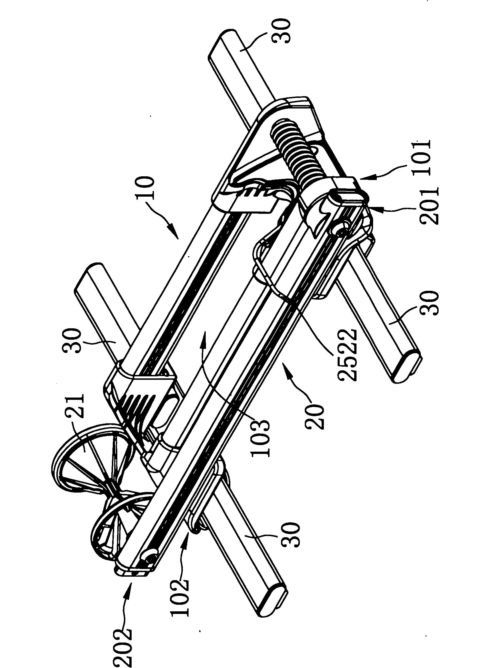
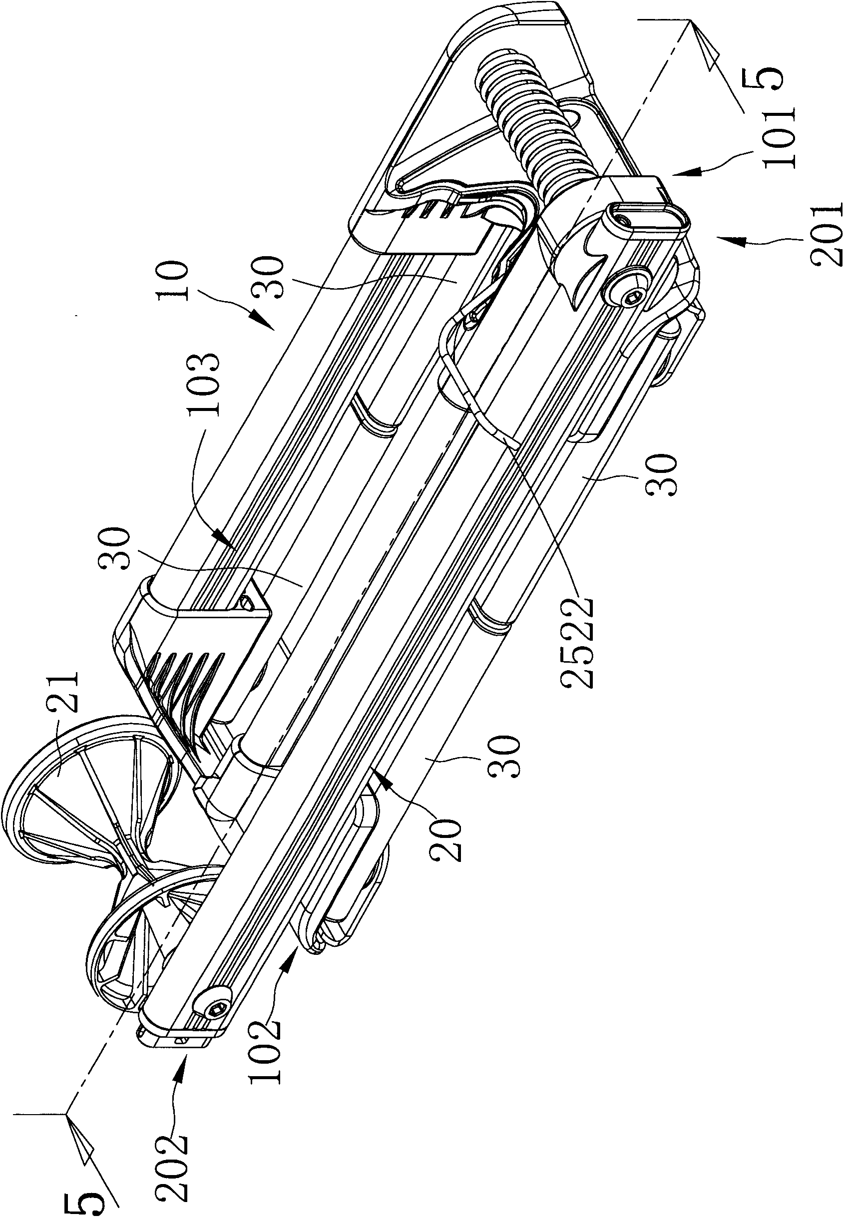
[0054] refer to figure 1 , figure 2 and image 3 , is a three-dimensional appearance view of the folding bicycle rack of the present invention. The foldable bicycle parking rack of the present invention includes: a base 10 , an abutting group 20 and several supporting feet 30 . The base 10 includes a first end 101 and a second end 102, and a receiving portion 103 is formed between the two ends 101, 102, and the receiving portion 103 is capable of parking bicycle wheels. The abutment group 20 includes a first end 201 and a second end 202. The first end 201 of the abutment group 20 is pivotally connected to the first end 101 of the base 10. The second end 202 of the abutment group 20 is provided with an abutment...


PUM


Abstract

The invention relates to a folding bicycle parking frame which comprises a base, a butting assembly and a plurality of supporting legs, wherein an accommodating part is formed between both ends of the base; the accommodating part can be used for parking a wheel of a bicycle; a first end of the butting assembly is pivoted with a first end of the base; a second end of the butting assembly is provided with a butting part for controlling a second end of the butting assembly so that the butting assembly can be pivoted at a butting position and a folding position relative to the base; when the butting assembly is positioned at the butting position, the butting part can be butted against the wheel of the bicycle; when the butting assembly is positioned at the folding position, the butting assembly is folded in the base; the supporting legs are respectively pivoted at both ends of the base; the supporting legs can be pivoted at a first position and a second position; when the supporting legs are positioned at the first position, the supporting legs are unfolded relative to the base; and when the supporting legs are positioned at the second position, the supporting legs are folded in the base.

Description

technical field [0001] The invention relates to a bicycle parking frame, in particular to a foldable bicycle parking frame. Background technique [0002] Referring to U.S. Patent No. D372691 "BICYCLE STAND", it discloses a fixed bicycle parking rack. This traditional parking rack is composed of iron sheets and iron pipes, and it includes two iron pipes arranged in parallel. And a base made of bent iron sheets, wherein the base spans two iron pipes, and the base and the iron pipes are fixed by welding or other bonding means, in other words, the base and the iron pipes cannot be folded. Furthermore, the traditional parking rack further includes a vertical iron pipe, which is combined with the iron pipe of the base, and the vertical iron pipe is hooked by an elastic body to generate positioning, and the vertical iron pipe is limited by the elastic body. Due to the unique design, it can only swing in a single direction. The upright iron pipe is pressed against the feet of the e...

Claims


Application Information

Patent Timeline
Patent Type & Authority Applications(China)
IPC IPC(8): B62H3/08
Inventor 庄士文
Owner TOPEAK
Why Eureka
Try Eureka