
Vertical folded plating production line

An electroplating production line, folding technology, applied in the field of vertical folding electroplating production line, can solve the problems of increased labor intensity of equipment maintenance personnel, large friction resistance of the pressing plate type conductive wheel, large contact resistance of the conductive area, etc., to improve the electroplating effect, transmission Good stress effect and improved electroplating effect

Inactive Publication Date: 2011-08-10
黄方豹
View PDF7 Cites 2 Cited by
  • Summary
  • Abstract
  • Description
  • Claims
  • Application Information

AI Technical Summary

Problems solved by technology

Since there are many production processes that need to go through various electroplating processes on the electroplating production line, the factory building to accommodate the production line often needs to be more than 40 to 50 meters long, and the infrastructure investment is relatively large; in addition, the too long distance from the production line also makes process management, Increased labor intensity of patrol work, production operation and equipment maintenance personnel
[0003] At the same time, the traditional electroplating production line loads current on the strip or wire plated parts, and adopts the metal conductive column energization method. Although there are many styles of cathode conductive structures, they all have disadvantages. For example, although the metal sleeve type has a simple structure, the electrical contact is reliable. The frictional resistance of the pressure plate type conductive wheel is large, which makes the transmission difficult; at the same time, the conductive mode of loading current is point contact or line contact, so the conductive area is small and the contact resistance is large, which is easy to spark and generate heat

Method used


Image

  • Vertical folded plating production line
  • Vertical folded plating production line
  • Vertical folded plating production line

Examples


Embodiment Construction

[0017] Through specific examples, the present invention will be further described.

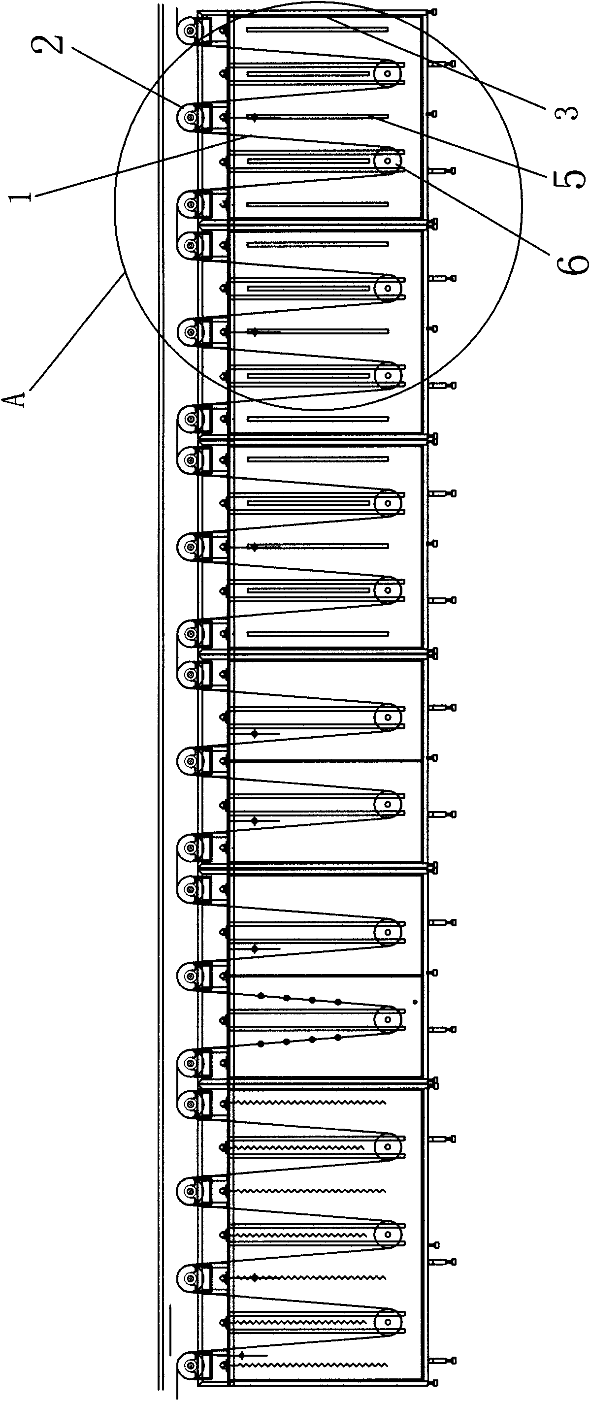
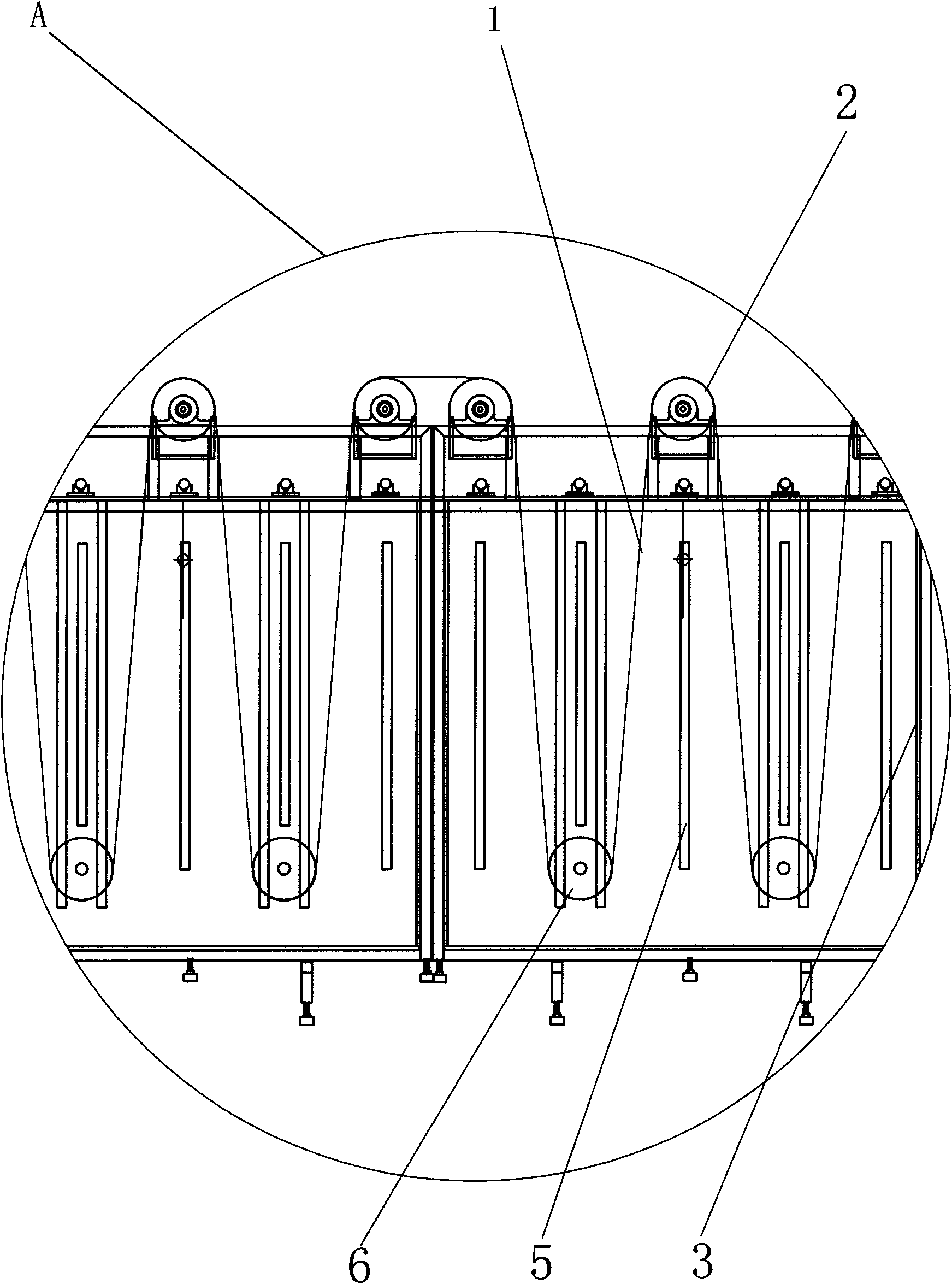
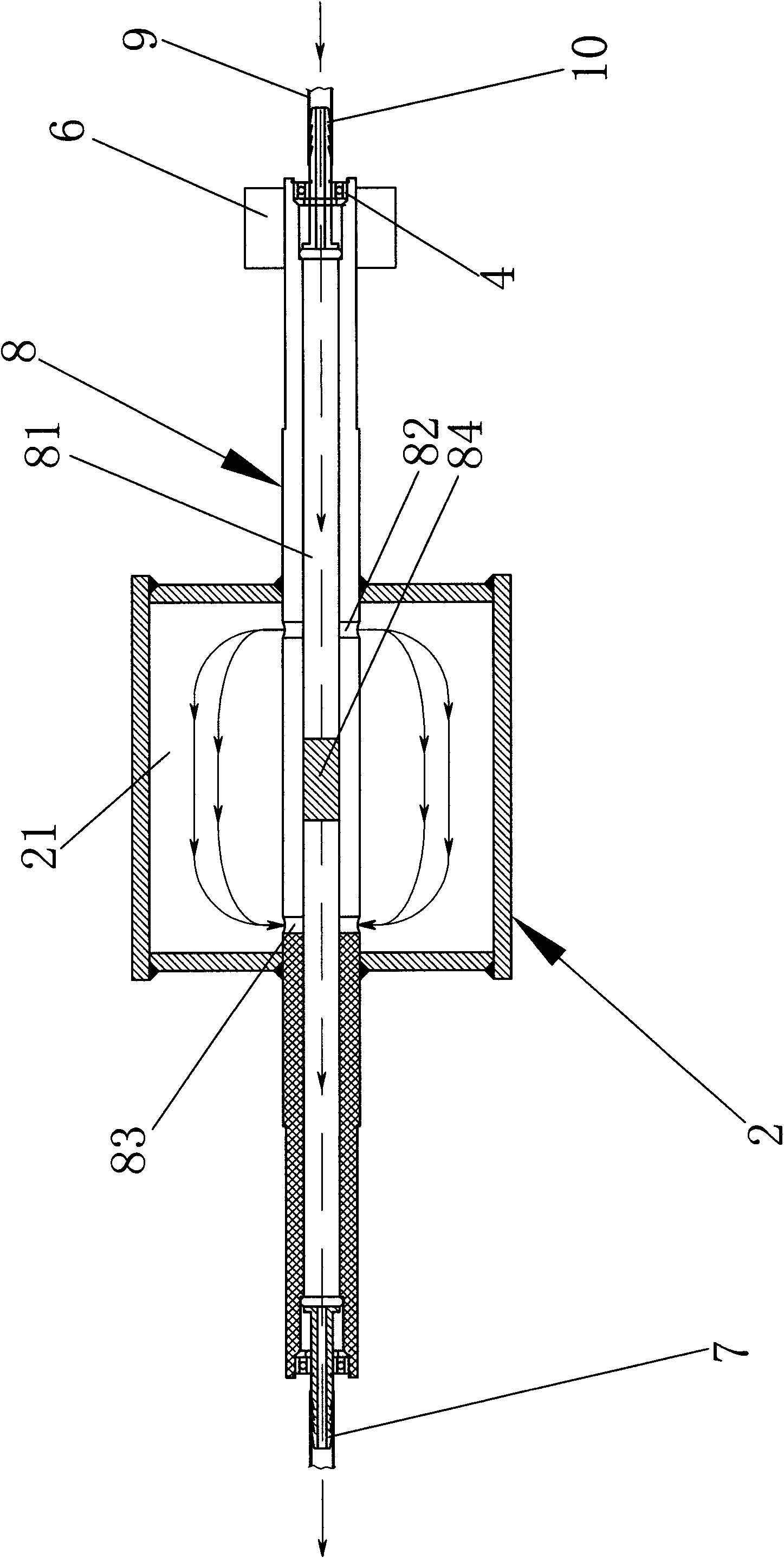
[0018] Such as figure 1 , the electroplating production line is composed of a plurality of electroplating process tanks 3 and multiple groups of electroplating wheel devices arranged in the electroplating process tank 3, and the electroplating process tank 3 is filled with different electroplating solutions or water, and electroplated parts of wire or strip 1. Through the conductive wheel 2 and the transmission wheel 6, the electroplating process tank 3 is turned up and down, and the plated material plate 5 is hung in the electroplating process tank 3. The anode of the electroplating power supply is connected to the plated material plate 5, and the cathode is connected to the plated material plate 5 through the brush 6. Conductive axle 8. During electroplating, the surface of the electroplating piece 1 is first degreased, cleaned, and activated, and then enters the electroplating process tank...


PUM


Abstract

The invention relates to a vertical folded plating production line, which comprises a plurality of plating process tanks and a plurality of groups of plating wheel devices arranged in the plating process tanks, wherein each group of plating wheel device comprises a conductive wheel, a driving wheel and a heat dissipation mechanism for realizing heat dissipation of the conductive wheel; the conductive wheel is arranged above the plating process tank and keeps a distance from plating solution in the plating process tank; the transmission wheel is arranged at the bottom of the plating process tank, corresponding to the lateral surface of the right lower part of the conductive wheel; and plating pieces run up and down, to and fro among the plating process tanks through the conductive wheels and the driving wheels in the plating wheel devices to form the vertical folded plating production line. The linear running mode of the strip or wire plating pieces is changed into an up and down fluctuating motion and folded running mode, the length of the traditional high-speed plating production line is shortened on the premise that the steps of the plating process are not reduced, and the plating effect is improved by arranging the heat dissipation mechanisms for realizing the heat dissipation of the conductive wheels.

Description

technical field [0001] The invention relates to an electroplating production device, in particular to a vertical folding electroplating production line. Background technique [0002] The traditional strip or wire high-speed electroplating production line generally adopts the linear transmission method, that is, the wire or strip plated parts are conveyed in a straight line, and the metal surface is processed through the various process plating tanks of the electroplating production line in the horizontal direction. Since there are many production processes that need to go through various electroplating processes on the electroplating production line, the factory building to accommodate the production line often needs to be more than 40 to 50 meters long, and the infrastructure investment is relatively large; in addition, the too long distance from the production line also makes process management, The labor intensity of patrol work, production operation and equipment mainten...

Claims


Application Information

Patent Timeline
IPC IPC(8): C25D7/06
Inventor 黄方豹
Owner 黄方豹
Features
  • Generate Ideas
  • Intellectual Property
  • Life Sciences
  • Materials
  • Tech Scout
  • Unparalleled Data Quality
  • Higher Quality Content
  • 60% Fewer Hallucinations
Learn More