Waste heat utilization system for internal combustion engine with antifreeze unit

A technology of internal combustion engine and waste heat circuit, which is applied in the direction of internal combustion piston engine, combustion engine, mechanical equipment, etc., and can solve the problems of medium freezing and so on.

Inactive Publication Date: 2011-08-10
MAN TRUCK & BUS OESTERR
View PDF3 Cites 4 Cited by
  • Summary
  • Abstract
  • Description
  • Claims
  • Application Information

AI Technical Summary

Problems solved by technology

[0005] Especially in the vehicular application of such systems, the big disadvantage of water is the problem of freezing of the medium

Method used


Image

  • Waste heat utilization system for internal combustion engine with antifreeze unit
  • Waste heat utilization system for internal combustion engine with antifreeze unit
  • Waste heat utilization system for internal combustion engine with antifreeze unit

Examples


Embodiment Construction

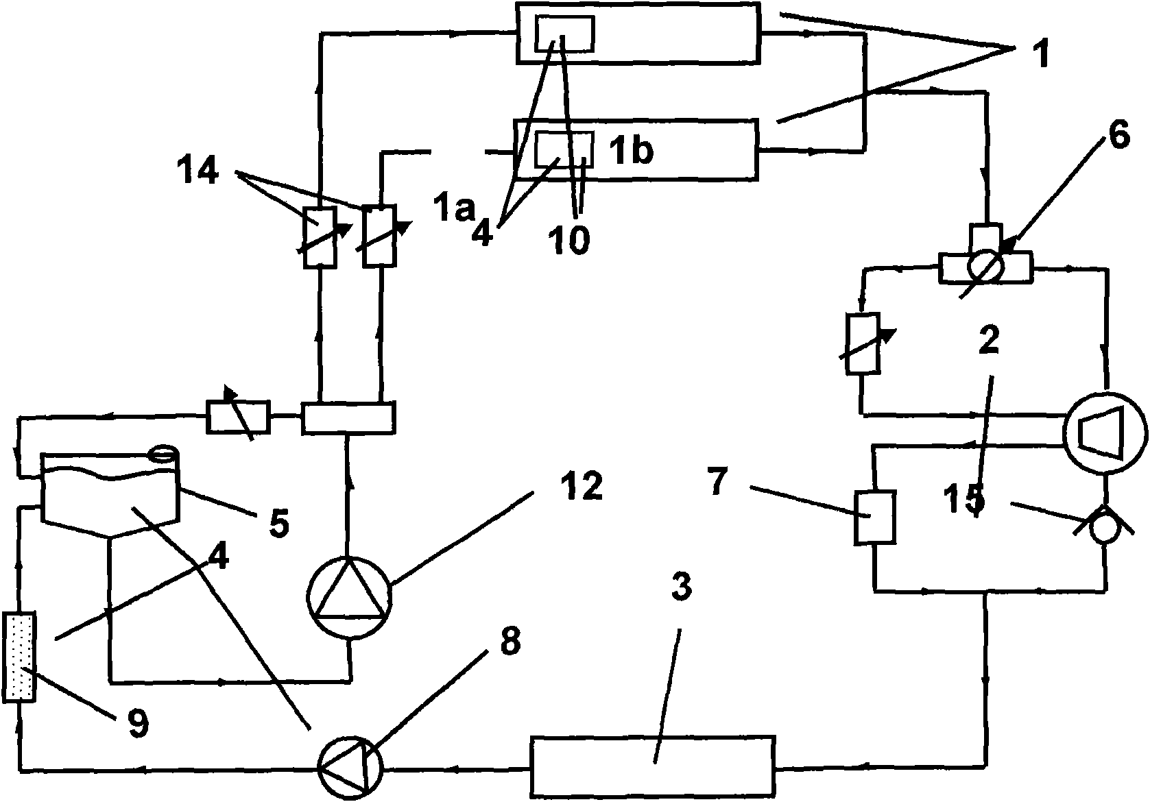
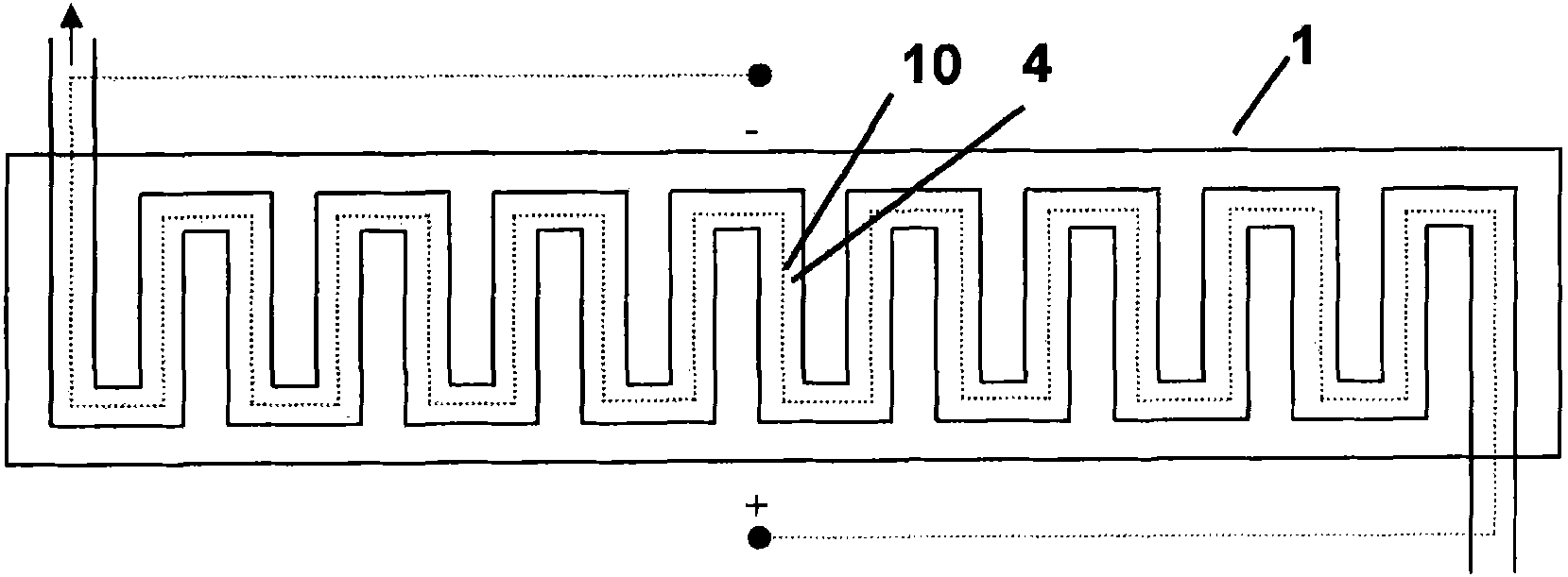
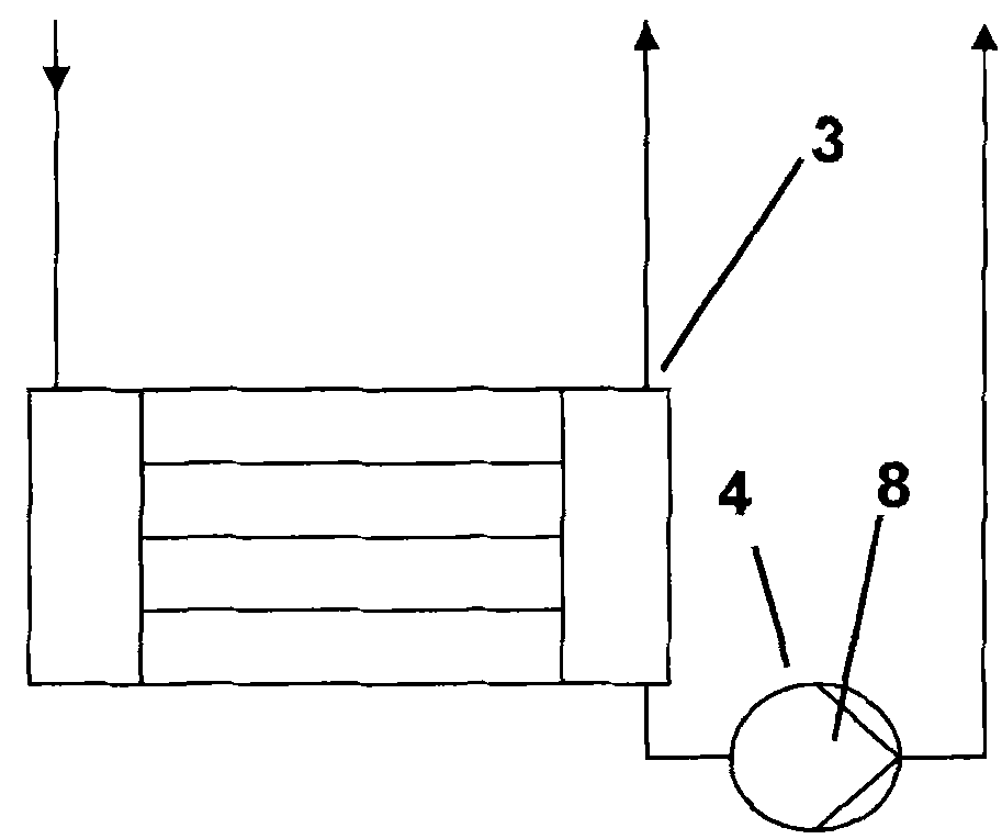
[0037] figure 1 Shown is a waste heat utilization circuit with which the waste heat of an internal combustion engine is converted into mechanical work. For this purpose, the waste heat generated in the internal combustion engine or in the exhaust system is first passed to the primary cooling circuit before it is supplied to the waste heat circuit designed as a secondary heat circuit. The main components required for waste heat utilization are: evaporator 1, in which the working fluid changes from liquid to vapor state; expansion unit 2, in which the working fluid in vapor state is decompressed, thereby outputting mechanical work ; Condenser, in which the working fluid is liquefied to its initial state before being evaporated.

[0038] elaborated below figure 1 The specifics of the device configuration shown in. The working fluid is input from the supply tank 5 into the waste heat utilization circuit by means of the supply pump 12 . The quantity of working fluid which is fe...


PUM


Abstract

Provided is a waste heat utilization system for an internal combustion engine with an antifreeze unit. The working medium circulates in the waste heat loop. The waste heat and or waste gas heat of the internal combustion engine is converted into mechanical work through the waste heat loop. The waste heat loop comprises an evaporator (1) where the working medium is partly converted into steam state of matter through absorbing the waste heat of the internal combustion engine, an expansion unit (2) for providing drive energy where the working medium with a part being in a steam state conducts pressure reduction, and a condenser (3) where the working medium is converted into a liquid state of matter. At least one antifreeze unit (4) is disposed in the waste heat loop, and the antifreeze unit can prevent damage in the waste heat loop due to working medium freezing.

Description

technical field [0001] The invention relates to a method and a device for utilization of waste heat of an internal combustion engine with a waste heat circuit in which a working medium circulates and through which the waste heat of the internal combustion engine is converted into mechanical work. The waste heat circuit has: an evaporator in which the working fluid is at least partially converted into a vapor-like state; an expansion unit for providing mechanical work in which the at least partially vapor-like working fluid is reduced pressure; condenser in which the working fluid is transformed into a liquid state of matter. Background technique [0002] In order to be able to achieve fuel savings, in particular for vehicle internal combustion engines, such as motor vehicle internal combustion engines, a distinction can currently be made in particular between two technical solutions. Especially in urban traffic and distributed traffic (Verteilerverkehr), due to the braking ...

Claims


Application Information

Patent Timeline
Patent Type & Authority Applications(China)
IPC IPC(8): F02G5/04
CPCF01K25/10Y02T10/166F01N5/02F02G5/00F01K23/065Y02T10/16F02G5/04Y02T10/12
Inventor G·拉布M·劳普J·克拉默
Owner MAN TRUCK & BUS OESTERR
Why Eureka
Try Eureka