Wind-to-electricity conversion device applicable to rail wagon vehicles

A technology for railway freight cars and conversion devices, which is applied to electromechanical devices, wind energy power generation, vehicle energy storage, etc., can solve problems such as unfavorable and effective use of wind energy, difficulty in automatic reversing, and difficulty in fixing, so as to ensure the utilization rate of wind energy and improve the reliability of the system. The effect of high efficiency and high utilization rate of wind energy

Inactive Publication Date: 2011-08-10
ANHUI HEXUN RAIL TRANSIT APPL TECH
View PDF8 Cites 5 Cited by
  • Summary
  • Abstract
  • Description
  • Claims
  • Application Information

AI Technical Summary

Problems solved by technology

[0006] Disadvantage 1: Existing wind power generation devices are too large
As a result, the installation height is high and it is difficult to fix at the bottom of limited railway wagons
[0009] Disadvantage 2: The existing wind power generation device cannot automatically change direction with the train running direction
[0010] Existing wind generators always rotate against the wind direction, and it is difficult to realize automatic reversing with the direction of train running, which is not conducive to the effective use of wind energy
[0011] Disadvantage 3: Existing wind power generation devices must not have dirt and garbage attached, and cannot be cleaned automatically
[0013] Disadvantage 4: Existing wind power plants are sensitive to vibration
[0015] Disadvantage 5: The wind vane of the existing wind power generation device is relatively large
However, so far, there are no reports of related products in China

Method used


Image

  • Wind-to-electricity conversion device applicable to rail wagon vehicles
  • Wind-to-electricity conversion device applicable to rail wagon vehicles
  • Wind-to-electricity conversion device applicable to rail wagon vehicles

Examples


Embodiment Construction

[0038] The present invention will be further described below with reference to the accompanying drawings in conjunction with the embodiments, so that those skilled in the art can better understand the present invention and implement it, but the given embodiments are not intended to limit the present invention.

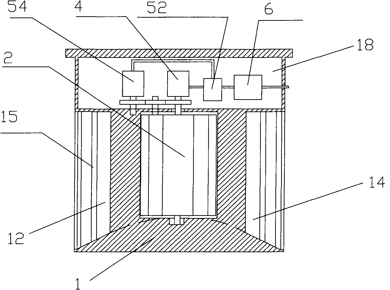
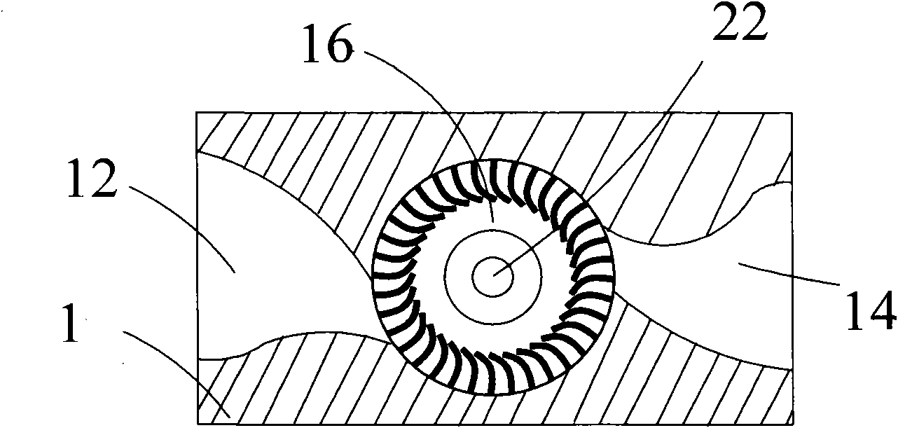
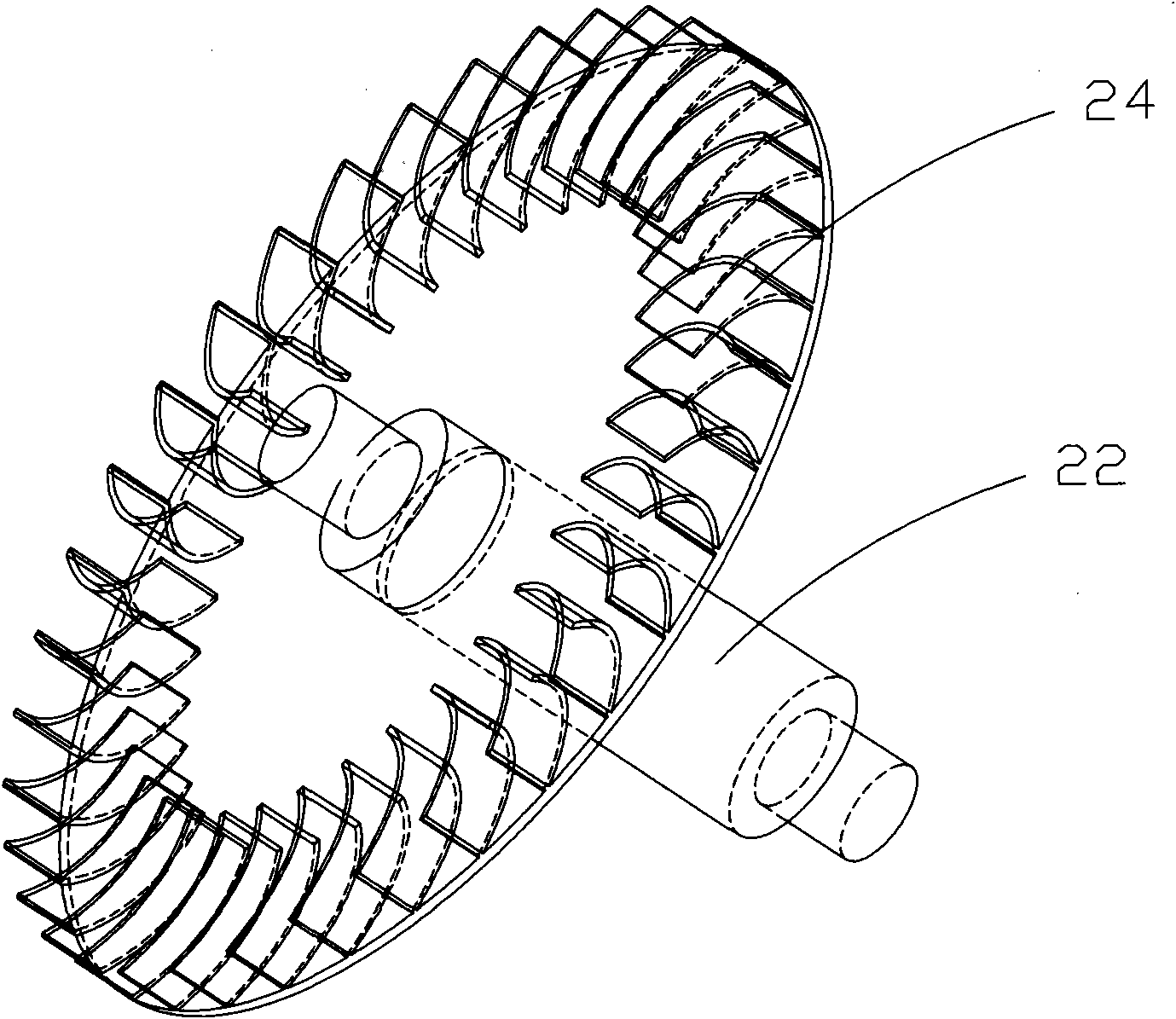
[0039] see Figure 1 to Figure 3 , the present invention is applicable to the wind power conversion device for railway freight vehicles, including a base 1 , a wind wheel 2 , a generator 4 , a monitoring system, and a power source 6 .

[0040] The base 1 is the installation and connection base of other components. The opposite sides of the base 1 are respectively provided with a first air duct 12 and a second air duct 14. The first air duct 12 and the second air duct 14 both adopt curved bell mouths. It is designed to make the speed of the air increase when the wind wheel 2 is pushed, so that the vehicle can reliably generate electricity even when the vehicle is runnin...


PUM


Abstract

The invention provides a wind-to-electricity conversion device applicable to rail wagon vehicles. The wind-to-electricity conversion device applicable to rail wagon vehicles comprises a base body, a wind wheel and a generator; a first wind channel and a second wind channel are formed on two opposite side faces of the base body respectively; the first wind channel and the second wind channel adopta curve flare opening design; a rotation cavity coaxial with the vertical central shaft of the base body is formed in the middle of the base body; the shaft of the wind wheel is rotatably fixed in the rotation cavity and connected with the shaft of the generator; a round disc is fixed on the shaft of the wind wheel; the round disc is coaxial with the shaft of the wind wheel; blades of the wind wheel are distributed on the circumference of the round disc uniformly; one blade of the wind wheel is c-shaped; and both the inner side openings of the first wind channel and the second wind channel face the inner arcs of the c-shaped blades. The wind-to-electricity conversion device applicable to rail wagon vehicles has the advantages of realizing bidirectional wind energy collection at the bottomof a train; and after the device is arranged on a wagon vehicle, the wagon vehicle has electricity, so the electricity basis is provided for realizing real-time monitoring of the train state, automatic control and the like in the future.

Description

【Technical field】 [0001] The invention relates to a power generation device for railway freight vehicles, in particular to a wind power conversion device suitable for railway freight vehicles. 【Background technique】 [0002] As a power generation method, wind power has been gradually promoted and put into use. Its working principle is that the wind energy is converted into the rotational mechanical energy of the generator shaft through the wind wheel of the fan, and then drives the rotor of the generator to rotate to realize the cutting of the magnetic force line to generate electricity. Wind turbines are generally installed at a position of more than ten to twenty meters above the ground, or even higher, and most of them are horizontal axis generators. In order to effectively utilize wind energy, traditional wind generators mainly increase the sweeping area, that is, the size of the wind rotor blades is larger; the fan is fixed on the ground and does not move relative to th...

Claims


Application Information

Patent Timeline
Patent Type & Authority Applications(China)
IPC IPC(8): F03D9/00F03D3/00F03D3/04F03D3/06B08B5/02B60L8/00H02K7/18F03D9/11F03D9/32
CPCY02E10/74Y02E10/72Y02T10/7083Y02T10/641Y02E10/728Y02E70/30Y02T10/64Y02T10/7072
Inventor 张永强刘维来赵腾飞
Owner ANHUI HEXUN RAIL TRANSIT APPL TECH
Why Eureka
Try Eureka