System for partially recovering byproduct heat of refrigerating unit
A technology of refrigeration unit and recovery system, which is applied in the direction of refrigerator, heating and refrigeration combination, refrigeration and liquefaction, etc. It can solve the problems of lower energy efficiency ratio, low recovery efficiency, high operating cost, etc., and achieve lower operation and maintenance costs and longer service life , The effect of improving the energy efficiency ratio
- Summary
- Abstract
- Description
- Claims
- Application Information
AI Technical Summary
Problems solved by technology
Method used
Image
Examples
Embodiment 1
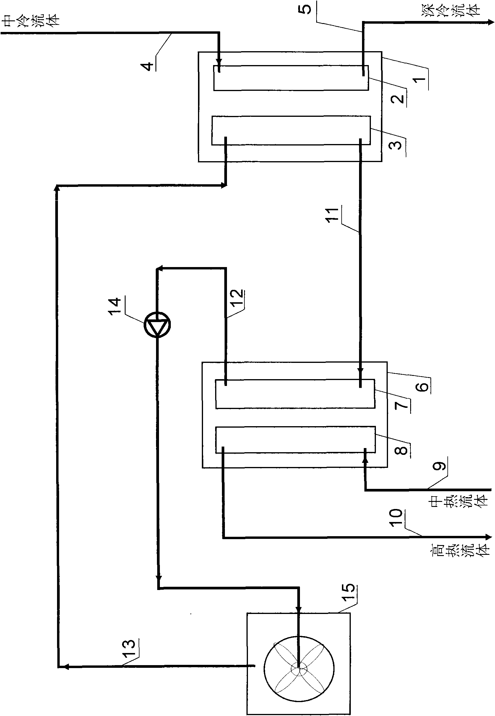
[0044] Embodiment 1: Compression cycle refrigerating machine, the cooling tower is at a high position, and the cold water is recirculated by its own weight, and the by-product heat recovery system of the refrigerating unit. See attached figure 1 .
[0045] In the present invention, a heat exhaust pipeline 11 is provided from the condenser 3 of the refrigeration unit to the evaporator 7 of the heat pump unit, a warm water pipeline 12 is provided from the outlet of the heat pump unit evaporator 7 to the cooling tower 15, and a circulation pump 14 is arranged on the warm water pipeline 12; the cooling tower 15 to set the cooling water pipeline 13 to the condenser 3 of the refrigerating unit.
[0046] According to known principles:
[0047] The compressor of the refrigerating unit 1 pressurizes the gaseous refrigerant and sends it to the condenser 3 of the refrigerating unit. The refrigerant becomes liquid and releases heat in the refrigeration unit condensing coil. The conden...
Embodiment 2
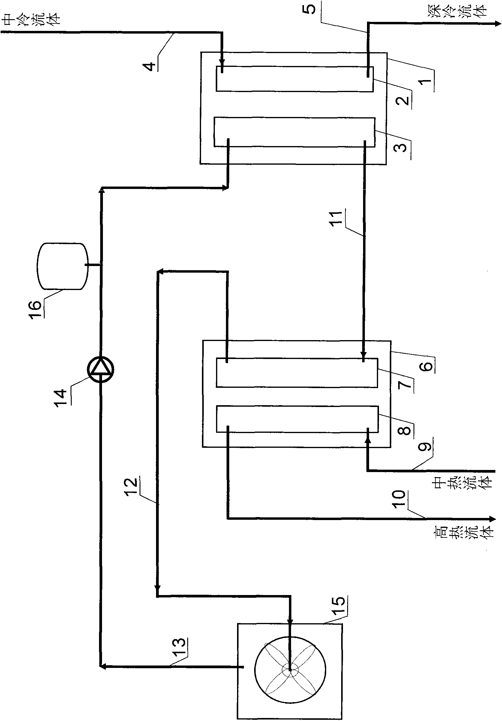
[0050] Embodiment 2: Compression cycle refrigerating machine, the cooling tower is at a low position, and the cold water is reclaimed by the by-product heat part of the refrigerating unit pumped back. See attached figure 2 .
[0051] In this system, the circulation pump 14 is arranged on the cooling water pipeline 13 . Since the cooling tower is at a low position, the cooling water return pressure is low, so the return flow power is provided by the circulation pump 14 . In order to stabilize the circulation system pressure, a buffer tank 16 is provided at the outlet of the circulation pump.
[0052] The working principles of the refrigeration unit and the heat pump unit are the same as in Embodiment 1.
[0053] The working principle of the system is the same as in Embodiment 1.
Embodiment 3
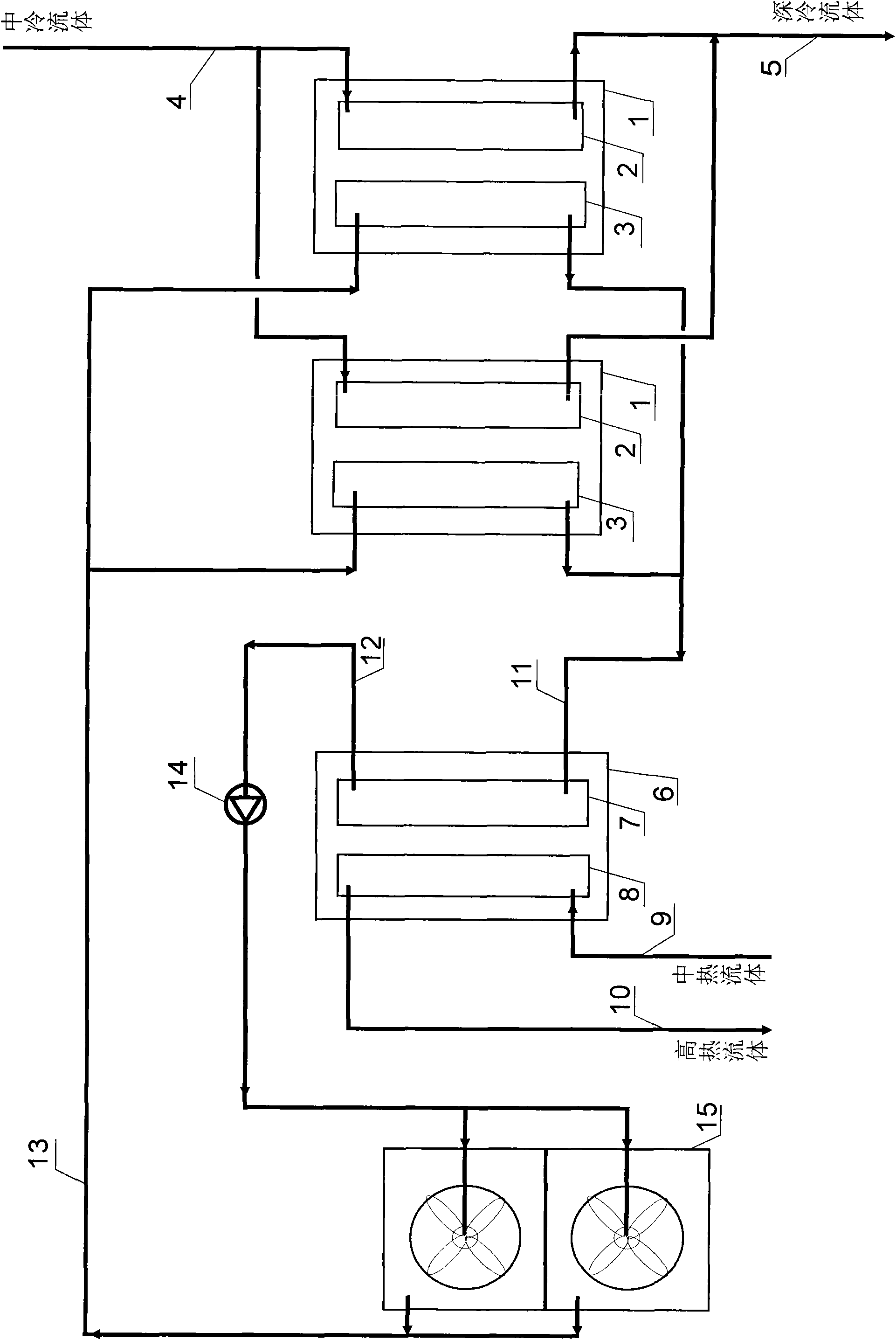
[0054] Embodiment 3: Two refrigeration units connected in parallel and two cooling towers connected in parallel to the system for recovering part of the by-product heat of the refrigeration unit. See attached image 3 .
[0055] In this system, the working principles of the refrigeration unit and the heat pump unit are the same as in Embodiment 1.
[0056] The working principle of the system is the same as in Embodiment 1.
[0057] The difference is:
[0058] The intercooling fluid inlet 4 is divided into two, through which the intercooling fluid enters the evaporators 2 of the two refrigeration units respectively; flow out.
[0059] The cooling pipeline 11 is combined into one, and the hot water flows out from the condensers 3 of the two refrigeration units respectively, and enters the heat pump evaporator 7 through this; the cooling water pipeline 13 is divided into two, and the cooling water returns to the two refrigeration units through this. Condenser of the unit 3. ...
PUM
 Abstract
Description
Claims
Application Information
 - R&D
- Intellectual Property
- Life Sciences
- Materials
- Tech Scout
- Unparalleled Data Quality
- Higher Quality Content
- 60% Fewer Hallucinations
Browse by: Latest US Patents, China's latest patents, Technical Efficacy Thesaurus, Application Domain, Technology Topic, Popular Technical Reports.
© 2025 PatSnap. All rights reserved.Legal|Privacy policy|Modern Slavery Act Transparency Statement|Sitemap|About US| Contact US: help@patsnap.com


