Fitting eccentric error compensating method based on CNC (Computerized Numerical Control) gear measuring center

A technology of gear measurement and compensation method, which is applied in the field of measurement, can solve problems affecting measurement accuracy, etc., and achieve the effect of improving measurement efficiency, reducing requirements, and realizing precise measurement

Inactive Publication Date: 2011-08-10
HARBIN INST OF TECH
View PDF5 Cites 32 Cited by
  • Summary
  • Abstract
  • Description
  • Claims
  • Application Information

AI Technical Summary

Problems solved by technology

[0004] The purpose of the present invention is to solve the problem that the measurement accuracy is affected due to the deviation of the geometric center of the gear from the center of r

Method used


Image

  • Fitting eccentric error compensating method based on CNC (Computerized Numerical Control) gear measuring center
  • Fitting eccentric error compensating method based on CNC (Computerized Numerical Control) gear measuring center
  • Fitting eccentric error compensating method based on CNC (Computerized Numerical Control) gear measuring center

Examples


specific Embodiment approach 1

[0027] Specific implementation mode one: this implementation mode comprises the following steps:

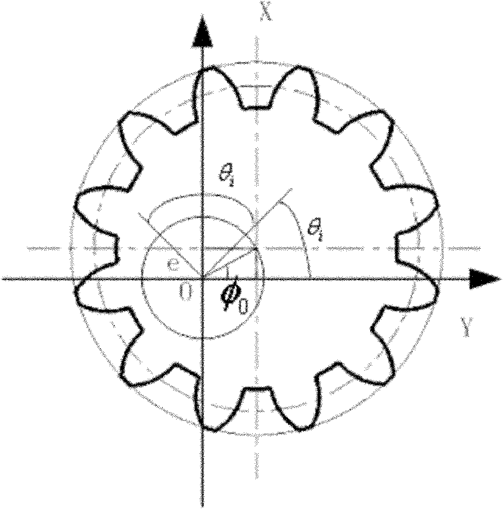
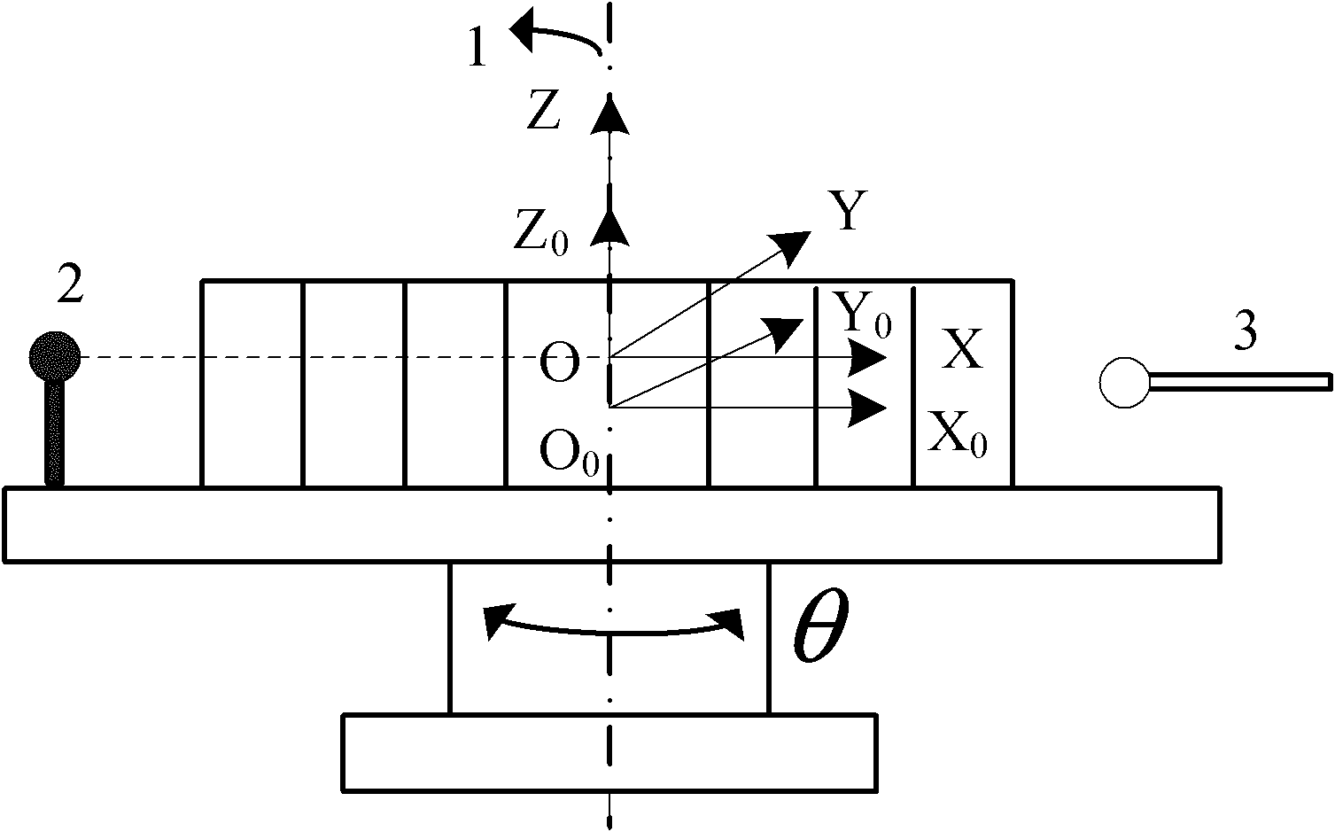
[0028] Step 1: Fix the workpiece to be measured on the measurement position of the CNC gear measurement center, establish the workpiece coordinate system with the geometric center of the workpiece to be measured as the origin, and make the X axis, Y axis and Z axis of the workpiece coordinate system and the instrument coordinate system The directions of the axes are the same; the instrument coordinate system is the coordinate system of the CNC gear measurement center;

[0029] Step 2: Calculate the conversion relationship between the instrument coordinate system and the workpiece coordinate system under the ideal measurement state;

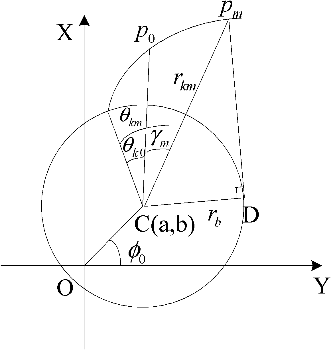
[0030] Step 3: Calculate the conversion relationship between the instrument coordinate system and the workpiece coordinate system in the eccentric measurement state, and obtain the expression of the clamping eccentric vector;

[0031] Step 4: Set th...

specific Embodiment approach 2

[0037] Embodiment 2: This embodiment is a further description of Embodiment 1. The ideal measurement state in step 2 is: the origin of the coordinate system obtained by translating the origin of the instrument coordinate system along its Z-axis direction is used as the origin of the workpiece coordinate system ;

[0038] The conversion relationship between the instrument coordinate system and the workpiece coordinate system under the ideal measurement state is:

[0039] x y z = x 0 y 0 z 0 + 0 ...

specific Embodiment approach 3

[0042] Embodiment 3: This embodiment is a further description of Embodiment 2. The conversion relationship between the instrument coordinate system and the workpiece coordinate system under the eccentric measurement state described in step 3 is:

[0043] x y z = x 0 y 0 z 0 + 0 0 c + β ,

[0044] In the formula, β is the clamping eccentric vector, and its expression is:

[0045] wh...


PUM


Abstract

The invention discloses a fitting eccentric error compensating method based on a CNC (Computerized Numerical Control) gear measuring center, belonging to the technical field of measurement and solving the problem that the measurement precision is influenced in the traditional gear measuring process because the geometric center of a gear deviates from an instrument center of gyration. The fitting eccentric error compensating method comprises the following steps of: firstly, establishing a workpiece coordinate system and an instrument coordinate system; acquiring an expression of a fitting eccentric vector by means of a transformational relation between the two coordinate systems in an eccentric measurement state; setting an initial eccentric parameter of a workpiece to be detected, and acquiring an expression of a polar angle of the deviation of an original point of the workpiece coordinate system from the original point of the instrument coordinate system; establishing the transformational relation between the two original points of the two coordinate systems in the fitting eccentric measuring state; transforming a measurement value of the workpiece to be detected into a spatial coordinate value in the instrument coordinate system; calculating the initial eccentric parameter value of the workpiece to be detected; calculating a fitting eccentric vector value; and compensating the measurement value for error evaluation. The fitting eccentric error compensating method disclosed by the invention is used for error compensation in the gear measuring process.

Description

technical field [0001] The invention relates to a clamping eccentricity error compensation method based on a CNC gear measurement center, belonging to the technical field of measurement. Background technique [0002] CNC Gear Measuring Center (Computerized Numerical Control Gear Measuring Center), as an efficient new precision measuring instrument, is a milestone in the transition of gear measurement technology from the classical manual method to the modern automatic testing technology. Its measurement principle is the electronic generation method. During the measurement process, the workpiece to be measured is required to be clamped at the ideal position of the instrument, that is, the geometric center of the workpiece to be measured is required to coincide with the center of rotation of the instrument. In the actual clamping process, manual clamping or manual clamping with low-precision measuring instruments are often used to assist clamping. Due to the limitations of the ...

Claims


Application Information

Patent Timeline
IPC IPC(8): G01M13/02G01B7/312G01B7/28
Inventor 唐文彦韩连福马强
Owner HARBIN INST OF TECH
Why Eureka
Try Eureka