Inserted inlaid butt welding structure of ceramic metal halide electrode

A ceramic metal halide lamp, inlaid technology, applied to the parts of gas discharge lamps and other directions, to achieve the effect of reasonable structure, high brittleness and low strength

Active Publication Date: 2011-08-10
佛山宁宇科技股份有限公司
View PDF4 Cites 1 Cited by
  • Summary
  • Abstract
  • Description
  • Claims
  • Application Information

AI Technical Summary

Problems solved by technology

[0003] The purpose of the present invention is to overcome the shortcomings of complex laser welding of the electrodes of the existing ceramic metal halide lamps, and to insert the electrodes of the ceramic metal halide lamps into a mosaic butt welding structure with good working effect

Method used


Image

  • Inserted inlaid butt welding structure of ceramic metal halide electrode
  • Inserted inlaid butt welding structure of ceramic metal halide electrode
  • Inserted inlaid butt welding structure of ceramic metal halide electrode

Examples


Embodiment 1

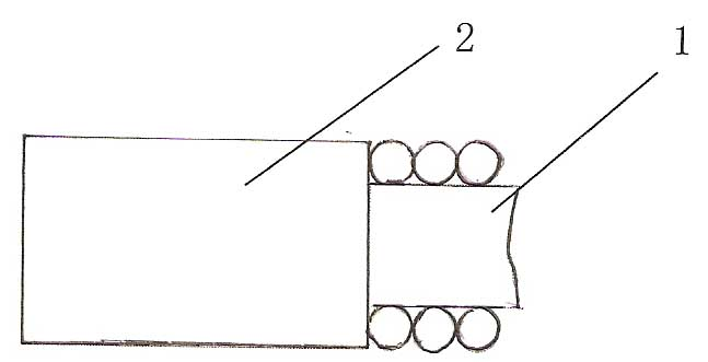
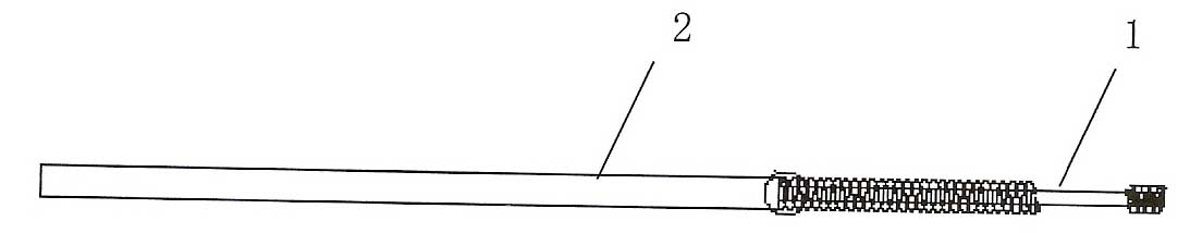
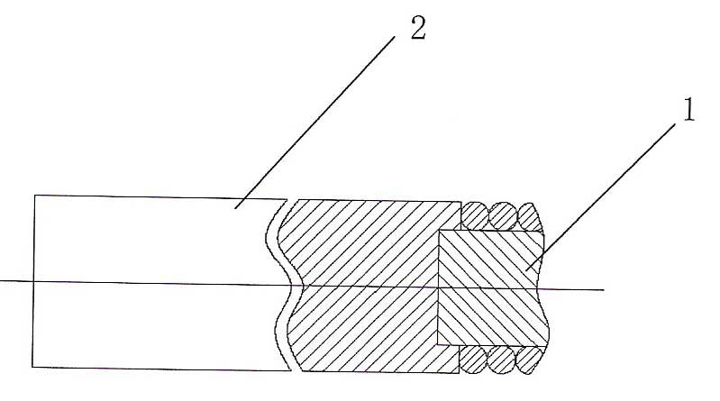
[0018] A ceramic metal halide lamp electrode insertion mosaic type butt welding structure, including the electrode main rod 1 and the lead-out rod 2, the electrode main rod is a tungsten electrode main rod, a molybdenum electrode main rod, an alloy tungsten electrode main rod or an alloy molybdenum electrode main rod The lead-out rod is a niobium lead-out rod or a niobium-zirconium alloy lead-out rod, one end of the electrode main rod is inserted into the end face of one end of the lead-out rod, and the outer wall of the insertion end of the electrode main rod is welded to the end face of the lead-out rod.

[0019] The surface of the insertion part of the lead-out rod and the electrode main rod is swollen upwards, and the diameter of the expansion part of the lead-out rod is 0.02mm~0.2mm larger than the diameter of the lead-out rod.

[0020] When the main rod of the electrode is inserted into the welding, it is carried out under the protection of inert gas.

Embodiment 2

[0022] The insertion end of the main rod of the electrode is in the form of chamfering, so that the expansion of the lead-out rod is small, and the rest is the same as that of embodiment 1.


PUM

PropertyMeasurementUnit
diameteraaaaaaaaaa

Abstract

The invention discloses an inserted inlaid butt welding structure of a ceramic metal halide electrode. An electrode main pole is a tungsten electrode main pole, molybdenum electrode main pole, alloy tungsten electrode main pole or alloy molybdenum electrode main pole; a lead-out pole is a niobium lead-out pole or niobium/zirconium alloy lead-out pole; one end of the electrode main pole is inserted into the end surface of one end of the lead-out pole; and the outer wall of the inserted end of the electrode main pole and the end surface of the lead-out pole are welded. The inserted inlaid structure disclosed by the invention is reasonable; the electrode main pole and the grain boundary of the niobium lead-out pole are fully melted; no seam or gap exists between a molybdenum sleeve and the niobium/zirconium pole; and the strength of the welding spot is high, and two-segment breakage is prevented in the case of 90-degree bending. Due to the close and perfect connection between the tungsten pole and niobium pole, the resistance consistence of the product is assured to be very high; and the quality hidden danger of air leakage in sealed connection of an electrode and a ceramic tube caused by the problems of rough welding spots, hollow welding, insufficient welding and the like of the current laser welding is effectively avoided.

Description

technical field [0001] The invention relates to an electrode structure of a ceramic metal halide lamp. Background technique [0002] In the prior art, the electrode of the ceramic metal halide lamp adopts the traditional laser welding method, such as figure 1 As shown: when the contact surface of the two round ends at the welding interface between the electrode main rod 1 and the lead-in rod cannot guarantee a perfect 90° right angle, there must be a gap at the end. At this time, laser welding can only achieve surface melting, and if high-power Laser welding to the center, as a result, the metal will collapse due to gravity when it reaches the melting point and air will be trapped during the rapid flow of niobium melt, so the butt joint cannot be achieved. Therefore, in order to maintain the original state of the surface, the laser can only be used on the shallow surface. If the fusion is carried out, there will be the following results: 1. The density of the contact layer ...

Claims


Application Information

Patent Timeline
Patent Type & Authority Applications(China)
IPC IPC(8): H01J61/04
Inventor 朱惠冲
Owner 佛山宁宇科技股份有限公司
Why Eureka
Try Eureka