Planar cutting tool and associated tool holder

A tool holder, cutting tool technology, applied in the direction of manufacturing tools, workpieces, drilling tool accessories, etc., can solve the problems of inaccuracy, difficult production, inferior tools, etc.

Inactive Publication Date: 2011-08-10
FAC
View PDF7 Cites 3 Cited by
  • Summary
  • Abstract
  • Description
  • Claims
  • Application Information

AI Technical Summary

Problems solved by technology

Therefore, there is a problem that the cutting material is not positioned on the tool axis, resulting in a poor quality tool
Furthermore, small tools are

Method used


Image

  • Planar cutting tool and associated tool holder
  • Planar cutting tool and associated tool holder
  • Planar cutting tool and associated tool holder

Examples


Embodiment Construction

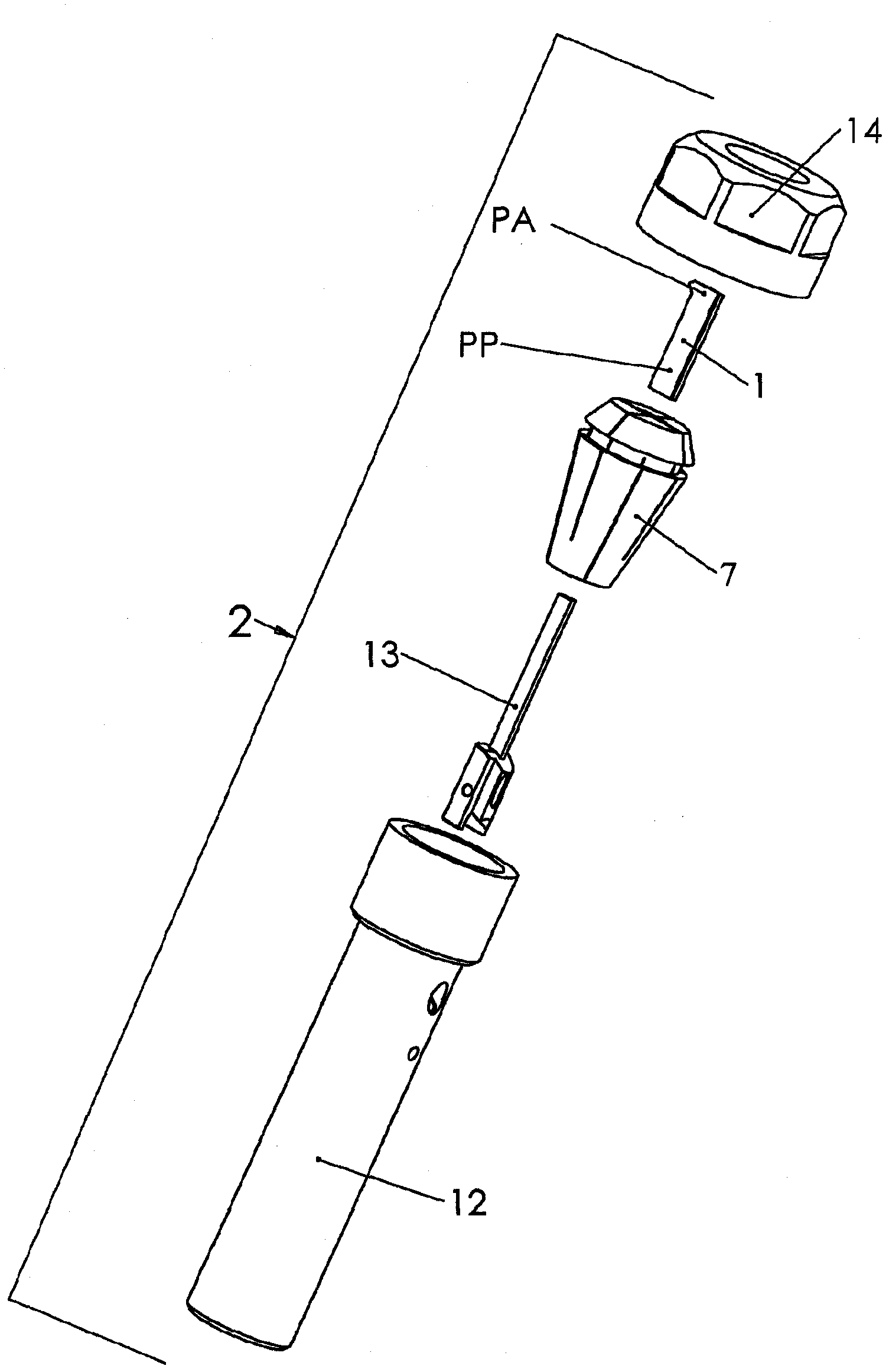
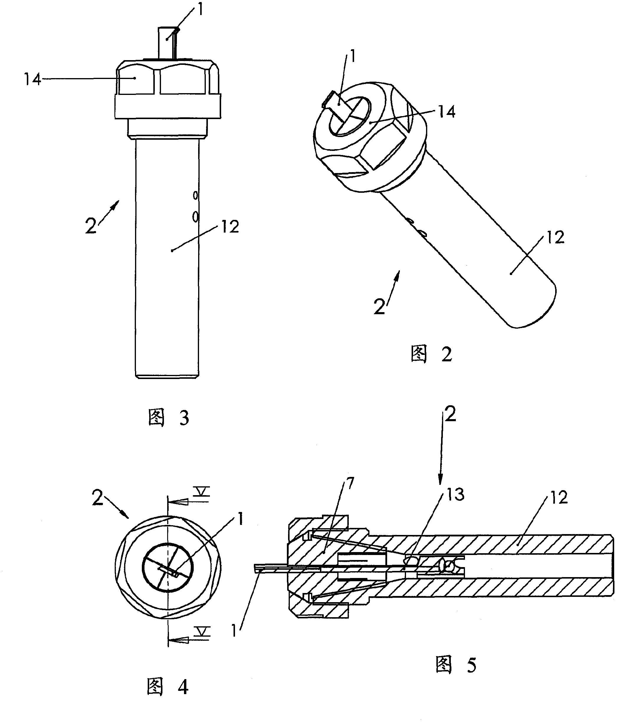
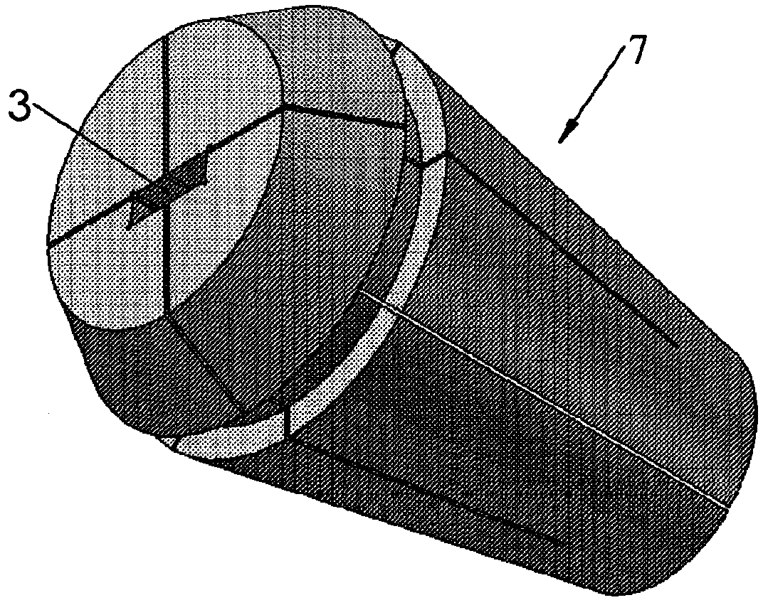
[0037] Depending on the use, the cutting tool 1 , 1A, 1B, 1C, 1D may be rotating or stationary, it is used for machining parts made of hard and / or abrasive materials, and the cutting tool 1 , 1A, 1B , 1C, 1D comprising: at least one active part whose hardness and / or abrasive properties are superior to those of the material to be machined; and a passive part for cooperating with the tool holder 2 including the gripper 7 .

[0038] According to a first characteristic of the invention, the active part "PA" and the passive part "PP" of said tool are formed by a one-piece plate delimiting these two parts to obtain a flat tool, which one-piece plate is obtained directly from the blank , the blank has a predetermined constant thickness and a hardness corresponding to the hardness of the active part "PA".

[0039] According to a second characteristic of the invention, the passive part "PP" of the same tooling plate is elongate and has a substantially quadrangular constant cross-sectio...


PUM


Abstract

The invention relates to a rotary or fixed cutting tool (1) for machining elements made of a hard and/or abrasive material, said tool comprising at least one active portion having hardness and/or abrasion properties higher than that of the material to be machined, and a passive portion interacting with a tool holder including a clamp (7), characterised in that the active portion (PA) and the passive portion (PP) of said tool are formed by an integral plate defining both portions and obtained directly from a blank having a predetermined constant thickness and a hardness corresponding to that of the active portion (PA) so as to obtain a planar tool, and in that the passive portion (PP) is elongate and has a constant substantially quadrangular cross-section for interaction with a housing (3) with a corresponding cross-section in the clamp (7), wherein the integral planar tool (1); thus formed is directly mounted in the housing (3) secured by tightening the same in the clamp (7).

Description

technical field [0001] The invention relates to a cutting tool, rotating or stationary, for machining parts made of hard and / or abrasive materials, the tool comprising: at least one active part, which hardness and / or abrasive properties superior to those of the material to be machined; and a passive part for cooperating with a tool holder comprising a gripper. Background technique [0002] It is known to make tools allowing this type of machining, comprising a cylinder made of carbide or steel, or other material, provided at the ends with spaces for the attachment of highly abrasive plates. [0003] The plates are connected by brazing, by screws passing through them and screwed into the tool body, or by retaining pins or the like. [0004] Once the boards are attached, the boards are sharpened as needed for cutting. [0005] This operation results in high costs for obtaining highly abrasive cutting tools. [0006] Known tools of this type tend to be placed between the jaw...

Claims


Application Information

Patent Timeline
IPC IPC(8): B23B31/20B23B51/00
CPCB23B51/107B23B27/007B23B51/0009B23B2226/125B23B31/202B23B2226/315B23B2231/2075B23B2231/2032Y10T407/2282Y10T407/14B23B51/00035
Inventor 安德烈·丘莱特
Owner FAC
Why Eureka
Try Eureka