Device for performing surface treatment on pole piece of lithium battery

A surface treatment device, lithium battery technology, applied in battery electrodes, circuits, electrical components, etc., can solve the problems of not increasing the output, short-circuiting the cells, puncturing the diaphragm, etc., to improve the quality of the pole pieces, and reduce the short-circuit rate. , high-quality effects

Inactive Publication Date: 2011-08-17
JIANGSU YINGTAI ELECTRONICS
0 Cites 18 Cited by

AI-Extracted Technical Summary

Problems solved by technology

[0003] The first method of brushing the pole piece with a sponge block is that the operator uses the method of brushing the front and back sides sequentially. During the brushing process, due to the repeated flipping of the pole piece, burrs are formed on the edge of the pole piece, which will be punctured in the next ...

Method used

[0014] The lower sponge 9 is provided with a number of through holes 10. The throug...

Abstract

The invention discloses a device for performing surface treatment on a pole piece of a lithium battery. In one piece-brushing process, the front side and the reverse side of the pole piece can be treated simultaneously, so that the treatment efficiency can be improved and the treatment quality can be guaranteed. The device comprises a machine frame, a workbench, an upper sponge, a lower sponge, a negative pressure device and an upper sponge driving cylinder; the lower sponge is fixed on the workbench; the upper sponge driving cylinder is arranged on the machine frame; a piston rod of the upper sponge driving cylinder faces downward; the bottom of the piston rod is fixedly connected with the upper sponge; the upper sponge is positioned above the lower sponge; the negative pressure device comprises an air compressor and a suction pipe; the suction pipe is inserted upward from the bottom of the workbench; and the pipe orifice of the suction pipe is positioned in the lower sponge. The process for brushing the piece is improved, a technology for automatically brushing the two sides of the piece simultaneously is adopted, two sponge plates which are correspondingly arranged up and down are used and when dust adsorbed to the sponge plates is more, the sponge plates can be replaced at any time. The device is high in quality for cleaning the pole piece, and high in yield, and can timely remove the dust and debris and obviously improve the quality of the pole piece, and the battery manufactured by the pole piece is low in short circuit rate.

Application Domain

Technology Topic

Treatment qualitySurface finishing +6

Image

  • Device for performing surface treatment on pole piece of lithium battery
  • Device for performing surface treatment on pole piece of lithium battery

Examples

  • Experimental program(1)

Example Embodiment

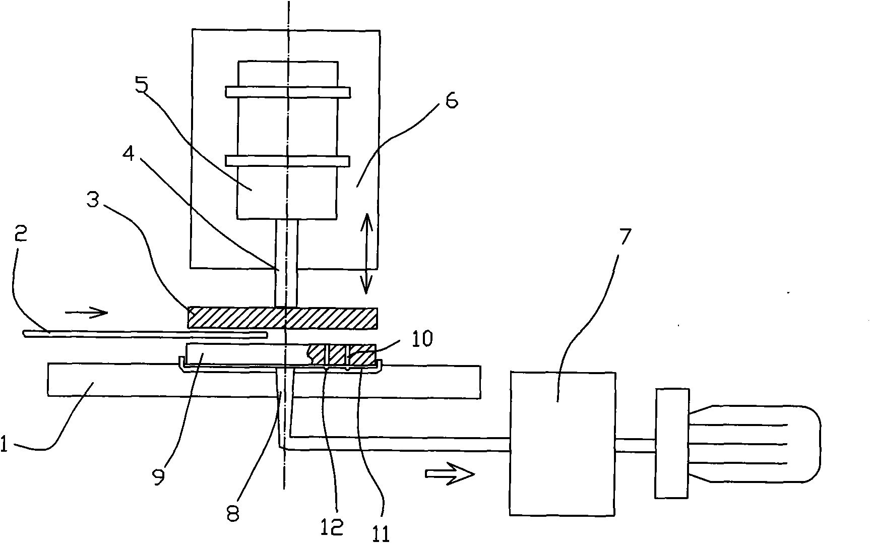
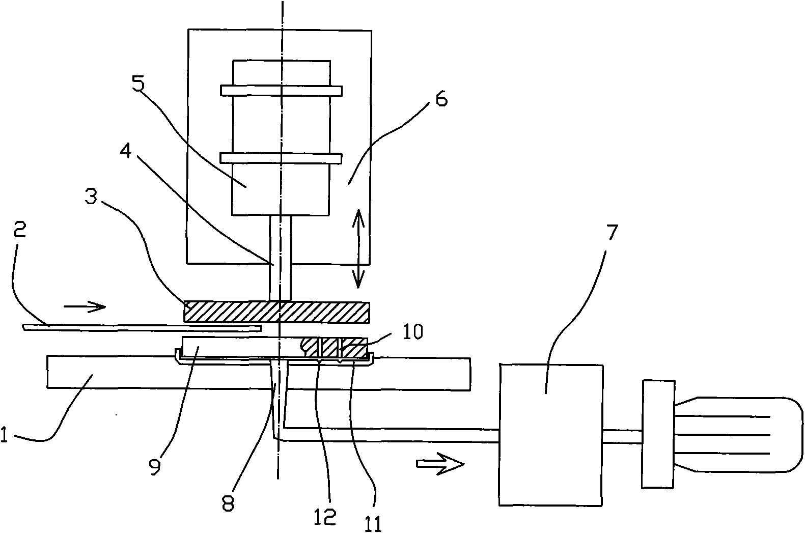
[0012] The present invention as figure 1 Shown, comprise frame 6, workbench 1, also comprise upper sponge 3, lower sponge 9, negative pressure device and upper sponge drive cylinder 5; Described lower sponge 9 is fixedly arranged on workbench 1; Described upper sponge drives The cylinder 5 is arranged on the frame 6, and the piston rod 4 of the upper sponge drive cylinder 5 faces downward, and the bottom end of the piston rod 4 is fixedly connected to the upper sponge 3, and the upper sponge 3 is positioned above the lower sponge 9; The negative pressure device includes an air compressor and a suction pipe 8 (the dust storage tank 7 is installed in the negative pressure pipeline to prevent secondary pollution), the suction pipe 8 runs upward from the bottom of the workbench 1, and the mouth of the suction pipe 8 is located in the Lower sponge 9 inside.
[0013] A tray 11 for supporting the lower sponge 9 is provided on the lower part of the lower sponge 9 , and a plurality of grooves 12 criss-crossing are provided on the tray 11 .
[0014] The lower sponge 9 is provided with several through holes 10 . The through holes 10 correspond to the trenches 12 so as to remove impurities more efficiently.
[0015] In specific applications, check whether the sponge board is clean before production, and when it is confirmed that the brushing machine has been turned on, put the pole piece 2 between the two sponge boards, and at the same time place the pole piece 2 between the sponge boards according to the center line in the illustration Gently drag in the direction of the arrow, and utilize the effect of the driving cylinder 5 to apply a little pressure to the pole piece 2 (the trampling of the foot switch controls the action of the driving cylinder 5). During this operation, the photoelectric counter also worked. At the same time, during work, the negative pressure will continuously absorb the impurities processed by the upper sponge and the lower sponge.

PUM

no PUM

Description & Claims & Application Information

We can also present the details of the Description, Claims and Application information to help users get a comprehensive understanding of the technical details of the patent, such as background art, summary of invention, brief description of drawings, description of embodiments, and other original content. On the other hand, users can also determine the specific scope of protection of the technology through the list of claims; as well as understand the changes in the life cycle of the technology with the presentation of the patent timeline. Login to view more.

Similar technology patents

Method for preparing silicone hydrogels

ActiveUS20070132949A1Quality improvementReduced polymerization shrinkageOptical articlesCeramic shaping apparatusSilicone hydrogelLow modulus
Owner:ALCON INC

Method of and system for capturing data

InactiveUS20070033064A1Quality improvementOffice automationResourcesPositional candidateData science
Owner:ABRAHAMSOHN DANIEL ALBERT ARKIND

Classification and recommendation of technical efficacy words

Why Eureka
Try Eureka