Method for welding heat exchanger tube plate and welding joint of heat exchange tube

A welding method and welding joint technology, applied in welding equipment, arc welding equipment, heat exchange equipment, etc., can solve problems such as shell-side medium gap corrosion, decrease in weld density, and no technical literature found, so as to improve the internal quality , Reduce the probability of welding defects, avoid the effect of crevice corrosion

Inactive Publication Date: 2011-08-17
TIANJIN JINBIN PETROCHEM EQUIP
View PDF7 Cites 29 Cited by
  • Summary
  • Abstract
  • Description
  • Claims
  • Application Information

AI Technical Summary

Problems solved by technology

The above-mentioned conventional welded joints and welding methods have the following problems: 1. When the first layer is self-melting, incomplete penetration is formed at the root of the joint, leaving a large cavity, and the shell-side medium is easily formed in crevice corrosion, which affects Joint life; 2. The positions of the arc striking and arc

Method used


Image

  • Method for welding heat exchanger tube plate and welding joint of heat exchange tube
  • Method for welding heat exchanger tube plate and welding joint of heat exchange tube
  • Method for welding heat exchanger tube plate and welding joint of heat exchange tube

Examples


Embodiment Construction

[0020] The present invention will be further described in detail below in conjunction with the accompanying drawings and through specific embodiments. The following embodiments are only descriptive, not restrictive, and cannot limit the protection scope of the present invention.

[0021] A method for manufacturing a welded joint between a heat exchanger tube sheet and a heat exchange tube, the steps of the manufacturing method are:

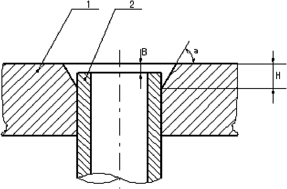
[0022] 1. Make a groove with an angle of a=2×45° on the heat exchange tube hole 2 on the tube sheet 1, and at the same time, recess the tube end of the heat exchange tube into the surface of the tube sheet to a height of B=0.5-1mm. The height is H=2mm;

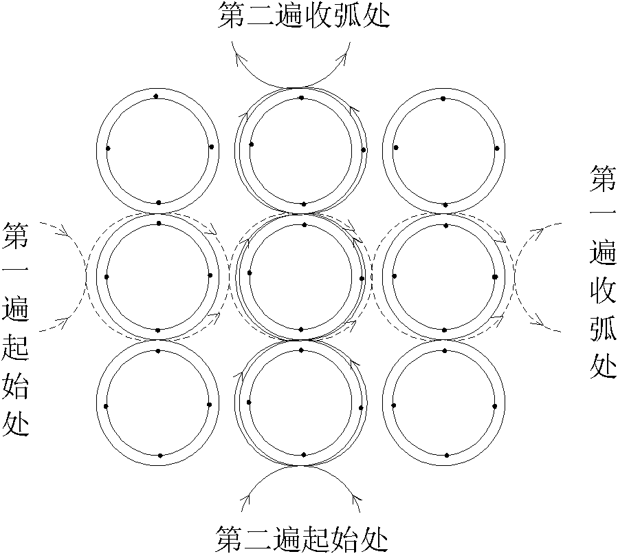
[0023] 2. Tungsten argon arc welding is used for welding, and the welding is divided into two times. The first welding adopts argon tungsten arc welding without adding welding wire, that is, self-fluxing welding. During welding, the pipes in the same column are welded sequentially from bottom to t...


PUM

PropertyMeasurementUnit
Heightaaaaaaaaaa
Heightaaaaaaaaaa

Abstract

The invention relates to a method for welding a heat exchanger tube plate and a welding joint of a heat exchange tube. During assembling of the heat exchange tube and the tube plate, a structure which is sunken into the surface of the tube plate 0.5 to 1 millimeter is adopted; during welding, a welding sequence from bottom to top is adopted, and a 3-shaped or S-shaped welding running line is adopted; during welding, each heat exchange tube is welded with a half of a cycle, and after 8 to 10 heat exchange tubes are welded disposably without arc quenching, the tube plate is subjected to the arc quenching; and according to the same method, the other half of the cycle is welded from bottom to top. Therefore, the frequency of arc stopping and arc starting can be reduced, the welding efficiency is improved, and the number of arc starting and stopping points and the probability of generating welding defects can be reduced. During welding, a tungsten electrode can be stretched into the root part of an included angle between the heat exchange tube and the tube plate easily; during autogenous welding, an electric arc can get to a sharp corner position, and the root part can be penetrated totally without any hollow cavity, so retention of shell side corrosion media is prevented, interval corrosion is avoided and the service life of a welding line is prolonged.

Description

technical field [0001] The invention belongs to the field of welding, and relates to a welding joint applied to a tube plate and a heat exchange tube of a tube-and-tube heat exchanger, in particular to a welding method for a tube plate and a heat exchange tube welding joint of a heat exchanger. Background technique [0002] In chemical equipment, the tube-and-tube heat exchanger is an important piece of equipment, and the welded joint between the tube sheet and the heat exchange tube is the most important and most likely to fail in the equipment, and its quality directly affects the quality of the equipment. Service life and stability of the device. At present, the connection joints between heat exchange tubes and tube sheets of heat exchangers are divided into two types according to different working conditions: fusion head type and fillet weld type. In the usual fusion head joint, the heat exchange tube hole on the tube plate is grooved at 2×45°. When assembling, the heat...

Claims


Application Information

Patent Timeline
IPC IPC(8): B23K101/14B23K9/167
Inventor 牛仲凯窦双云李相明赵丽辉何兵
Owner TIANJIN JINBIN PETROCHEM EQUIP
Why Eureka
Try Eureka