Precision vibration mirror correction system and method

A correction system and precise technology, applied in welding equipment, laser welding equipment, metal processing equipment, etc., can solve the problems of adverse effects of galvanometer correction, large calculation errors, etc., achieve stable mechanism, easy operation, and ensure measurement accuracy.

Inactive Publication Date: 2011-08-17
BEIJING JCZ TECH
View PDF4 Cites 58 Cited by
  • Summary
  • Abstract
  • Description
  • Claims
  • Application Information

AI Technical Summary

Problems solved by technology

[0005] In order to overcome the shortcomings of the existing galvanometer correction system that the calculation error of the position deviation of each mark point is relatively large, which has an adverse effect on the galvanometer correction, the purpose of the present invention is to provide a precise galvanometer correction system and correction The method, the correction system and the correction method can carry out high-precision correction on the vibrating mirror, and the structure is simple, and the operation is simple and fast

Method used


Image

  • Precision vibration mirror correction system and method
  • Precision vibration mirror correction system and method
  • Precision vibration mirror correction system and method

Examples


Embodiment Construction

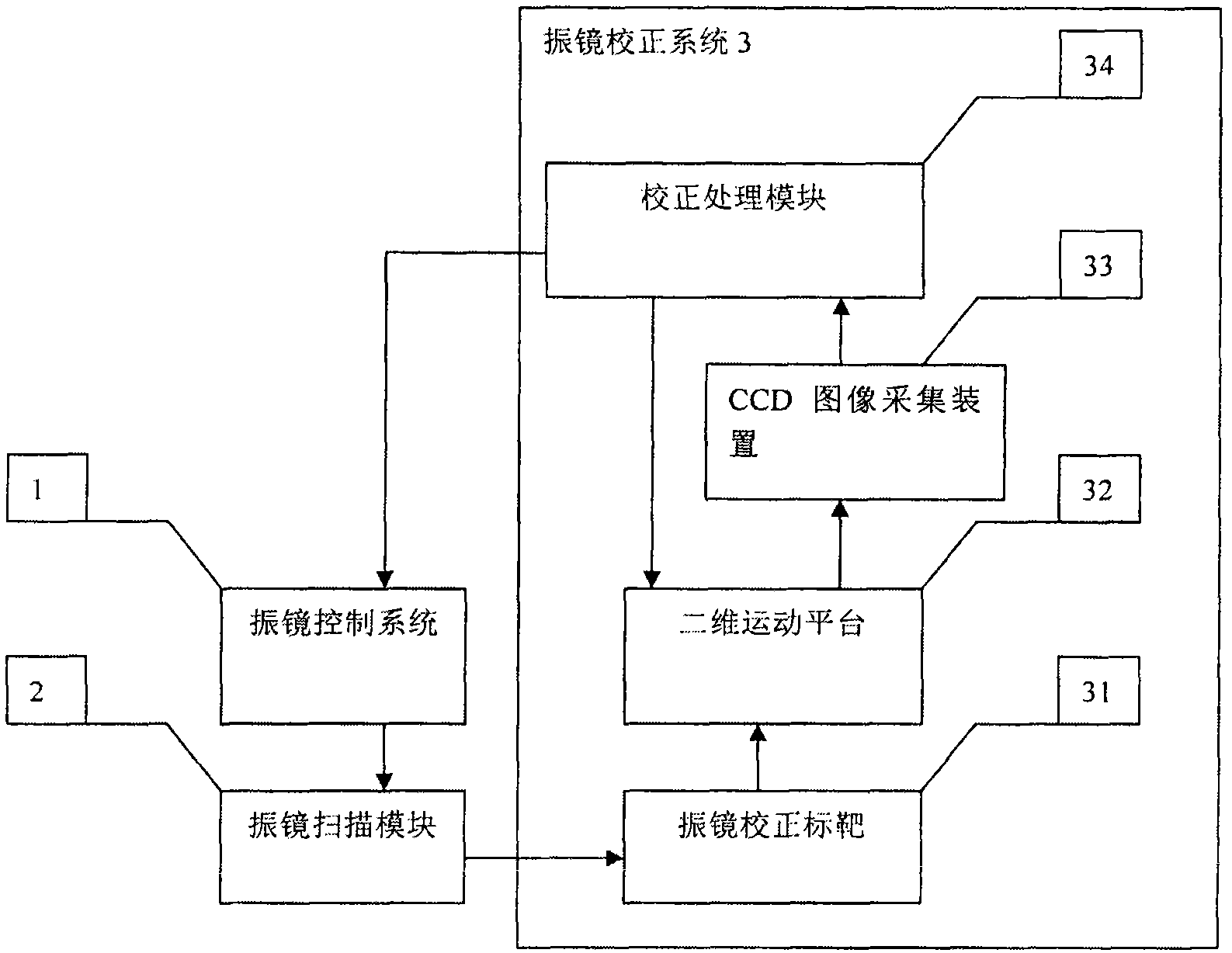
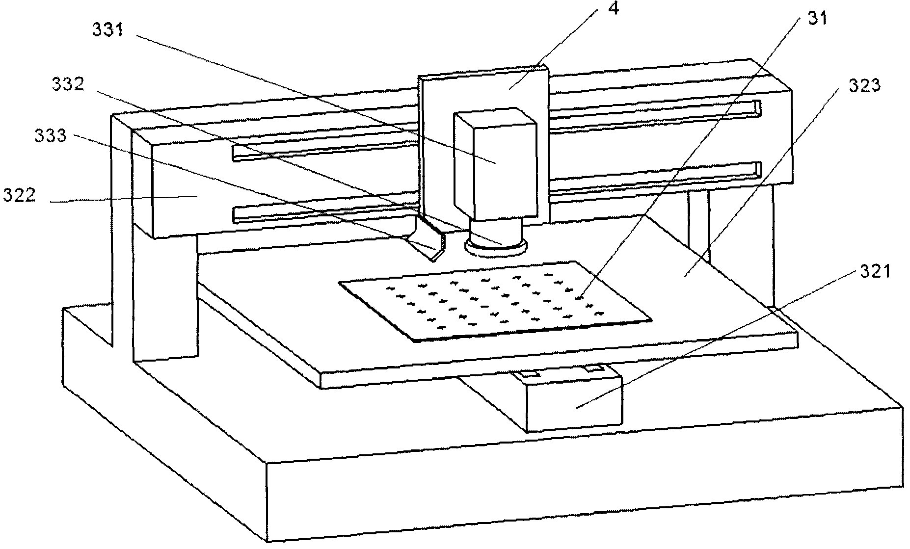
[0034] figure 1 Shown is an embodiment of the module structure of the precise galvanometer correction system of the present invention, image 3 Shown as figure 1 An embodiment of the assembly structure of the precision galvanometer correction system. Such as figure 1 with image 3 As shown, the galvanometer correction system 3 includes a galvanometer correction target 31, a two-dimensional motion platform 32, a CCD image acquisition device 33, and a correction processing module 34. The galvanometer correction system 3 is installed on the fixed base 4, and a two-dimensional motion platform 32 is provided at the bottom of the galvanometer correction target 31. The two-dimensional motion platform 32 includes a Y linear motor 321, an X linear motor 322 and a working platform. 323. The Y linear motor 321 is arranged in the Y direction in the plane coordinate system, the X linear motor 322 is arranged in the X direction and above the Y linear motor 321, and the working platform 323 i...


PUM


Abstract

The invention is applicable to the technical field of laser processing, and provides a precision vibration mirror correction system and a precision vibration mirror correction method. The vibration mirror correction system comprises a vibration mirror correction target, a charge coupled device (CCD) image acquisition device, a two-dimensional motion platform device and a correction processing module, wherein an appointed mark point is marked on the correction target by a vibration mirror scanning module through laser reflection; the CCD image acquisition device performs image acquisition on a standard mark point marked by a vibration mirror; the two-dimensional motion platform device executes a high-precision positioning motion so as to guarantee the positioning precision; and the correction processing module calculates an image acquired by the CCD image acquisition device, finds out a position deflection of the mark point of the vibration mirror correction target and generates a vibration mirror compensation file to correct the vibration mirror. The vibration mirror correction system can realize high-precision correction of the vibration mirror conveniently and quickly.

Description

Technical field [0001] The invention belongs to the technical field of laser processing, and specifically relates to a precise galvanometer correction system and a correction method. Background technique [0002] In the field of laser processing, a large number of galvanometers are used for scanning processing. Due to the installation of galvanometers and various other reasons, the processed images in the scanning area will be deformed. However, the traditional manual measurement method is difficult to achieve 0.1 Positioning accuracy below mm. [0003] The publication date is August 26, 2009. The Chinese invention patent application with the application number 200910105786.2 discloses a galvanometer correction system and a correction method. The method uses a CCD image acquisition device to position the matrix target, and uses the correction processing module to output Compensation file for galvanometer. [0004] Compared with the traditional manual correction method, this method ...

Claims


Application Information

Patent Timeline
Patent Type & Authority Applications(China)
IPC IPC(8): B23K26/42B23K26/70
Inventor 邱勇
Owner BEIJING JCZ TECH
Why Eureka
Try Eureka