Special clamp for abrasive flow polishing of narrow flow passage closed impeller flow passage

An impeller flow channel and special fixture technology, applied in grinding/polishing equipment, surface polishing machine tools, abrasives, etc., can solve the problem of not being able to use narrow flow channel closed impeller flow channel polishing, etc., to achieve a simple structure and simplify the fixture. Structure, the effect of reducing resistance

Inactive Publication Date: 2011-08-17
DALIAN POLYTECHNIC UNIVERSITY
View PDF5 Cites 34 Cited by
  • Summary
  • Abstract
  • Description
  • Claims
  • Application Information

AI Technical Summary

Problems solved by technology

This fixture cannot be used to poli...

Method used


Image

  • Special clamp for abrasive flow polishing of narrow flow passage closed impeller flow passage
  • Special clamp for abrasive flow polishing of narrow flow passage closed impeller flow passage
  • Special clamp for abrasive flow polishing of narrow flow passage closed impeller flow passage

Examples


Embodiment Construction

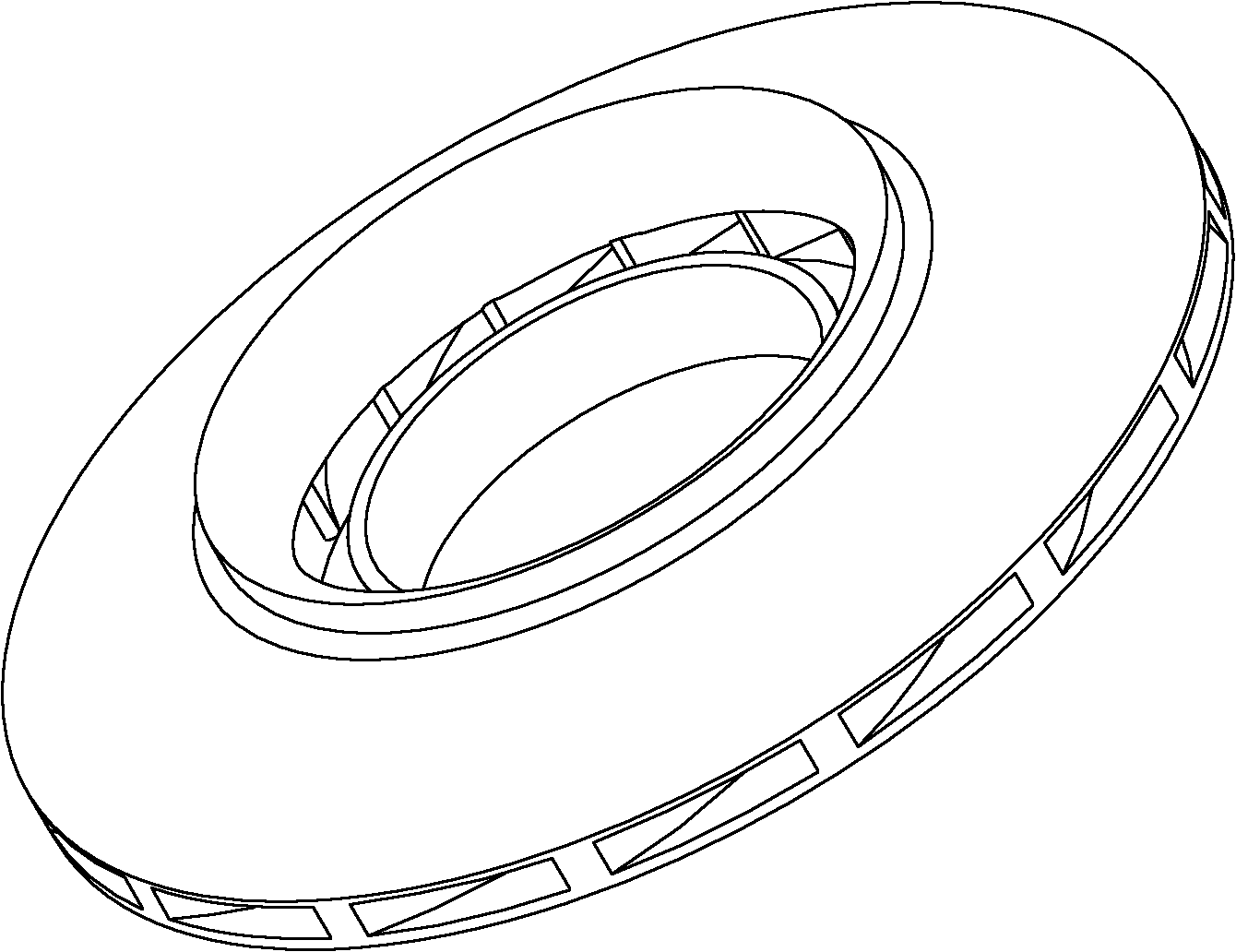
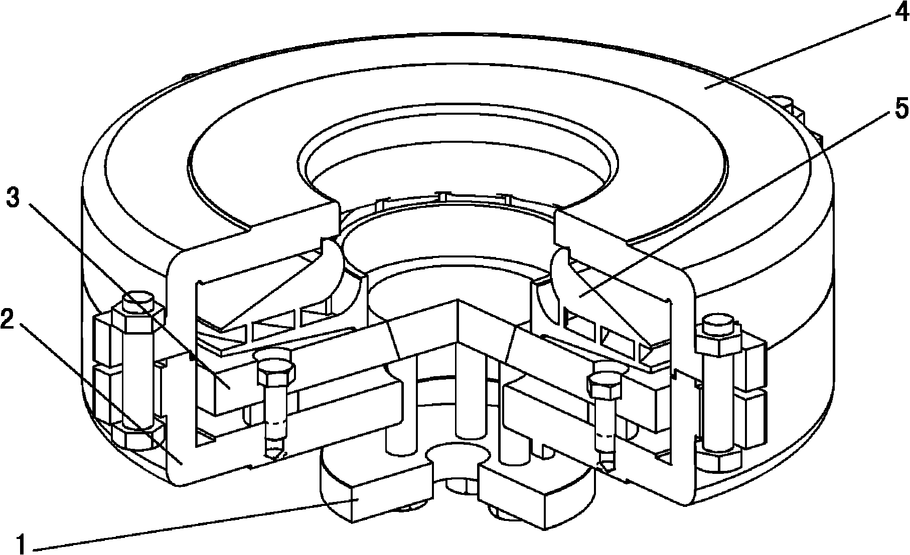
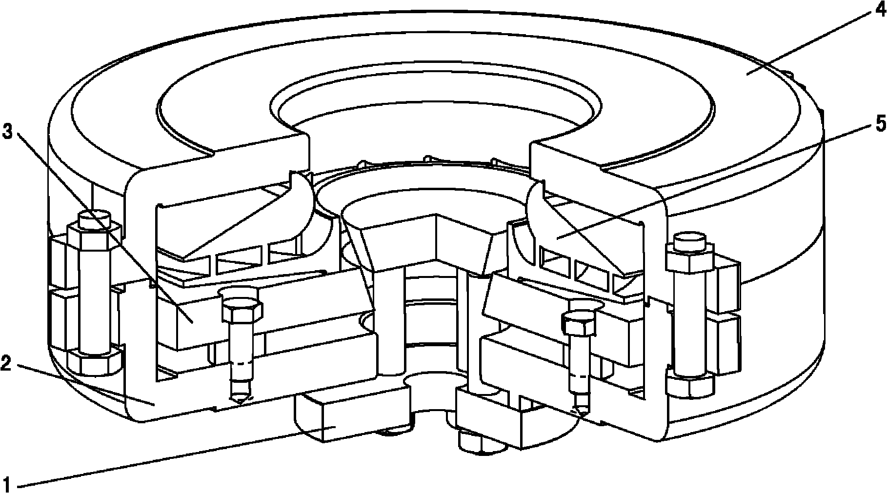
[0021] The present invention will be further described below in conjunction with the accompanying drawings. like Figure 2-3 As shown, a special fixture for abrasive flow polishing of a narrow channel closed impeller channel, including a floating lock 1, a lower mold body 2, a backing plate 3 and an upper mold body 4, and the upper mold body 4 and the lower mold body 2 are composed of A cylindrical cavity, its inner diameter is larger than the diameter of the impeller 5; the pad supporting plate 3 is a disk whose diameter is the same as that of the impeller 5, and is fixed on the lower mold body 2 by screws and washers. The central hole of the pad supporting plate 3 is Inverted tapered hole, and concentric with the center hole of the lower mold body 2; the floating lock 1 is composed of two upper and lower discs and studs and bolts connecting the two discs, passing through the backing plate 3 and the lower The center hole of the mold body 2, the upper disk of the floating loc...


PUM


Abstract

The invention discloses a special clamp for abrasive flow polishing of a narrow flow passage closed impeller flow passage. The special clamp comprises an upper mold, a lower mold, a floating lock and a gasket support plate, wherein the upper mold and the lower mold form a cylindrical cavity; the inner diameter of the cylindrical cavity is greater than the diameter of the impellers; the gasket support plate is a round disc having the diameter as the same as the diameter of the impellers; the floating lock consists of an upper round disc and a lower round disc and a double-head stud and a bolt which are used for connecting the two round discs; the mounted floating lock can move between the gasket support plate and the lower mold; the impellers are arranged on the gasket support plate, and are fastened by the upper mold and the lower mold; and the upper mold and the lower mold are positioned through seam allowance, and are fixed by the bolts. The clamp for abrasive flow machining of the narrow plow passage closed impellers can be used for fixing the impellers and can guide abrasive materials to flow through the surface of the impeller flow passage, and keep a given pressure so as to grind and polish the internal part of the impeller flow passage, form a circular loop and realize reciprocating flow of the abrasive materials.

Description

technical field [0001] The invention relates to a fixture for polishing a narrow-channel closed impeller for a centrifugal compressor, in particular to a special fixture for polishing a narrow-channel closed impeller flow channel abrasive flow. Background technique [0002] The surface roughness inside the narrow-channel closed impeller flow channel used in high-pressure small-flow centrifugal compressors will affect the mechanical efficiency and flow efficiency of the compressor, and it needs to be polished. [0003] Both theoretical calculation and actual measurement show that the surface roughness inside the channel of the impeller with this structure has a great influence on the efficiency of the compressor, and reducing the surface roughness of the impeller channel is an effective way to reduce power loss. This is recognized by the current compressor industry. If the existing surface roughness can be increased by two grades, its efficiency will be increased by 1% to 2%...

Claims


Application Information

Patent Timeline
IPC IPC(8): B24C3/32B24C9/00
CPCB24B31/006B24B31/116B24C3/327F01D25/285F04D29/023F04D29/284F05D2230/10F05D2230/68F05D2250/621F05D2300/516
Inventor 季田任志远
Owner DALIAN POLYTECHNIC UNIVERSITY
Why Eureka
Try Eureka