Thermal head control device

A control device and thermal head technology, applied in printing, printing plate preparation, etc., can solve the problems of lack of expressiveness of thin lines, dark color of printed matter, etc., and achieve the effects of shortening heating time, simple structure, and prolonging contact time

Inactive Publication Date: 2014-10-15
RISO KAGAKU CORP
View PDF6 Cites 0 Cited by
  • Summary
  • Abstract
  • Description
  • Claims
  • Application Information

AI Technical Summary

Problems solved by technology

[0004] However, in the case of perforating and performing stencil printing based on binary data, for example, when printing a full image (ベタタ like), such as Figure 19 As shown in the upper left figure of (when multi-valued is not performed), the overlapping portion increases due to dot gain (ドツトゲイン), so the color of the finished printed matter becomes darker than the specified color
In addition, there is also the problem of total blockage (ベタ冻まり) where isolated points are blocked.
And, in the case of printing photo images, such as Figure 19 As shown in the center left figure of , there is a problem of lack of expressiveness in expressing thin lines and smooth lines due to dot enlargement and dot bonding.

Method used


Image

  • Thermal head control device
  • Thermal head control device
  • Thermal head control device

Examples


Embodiment Construction

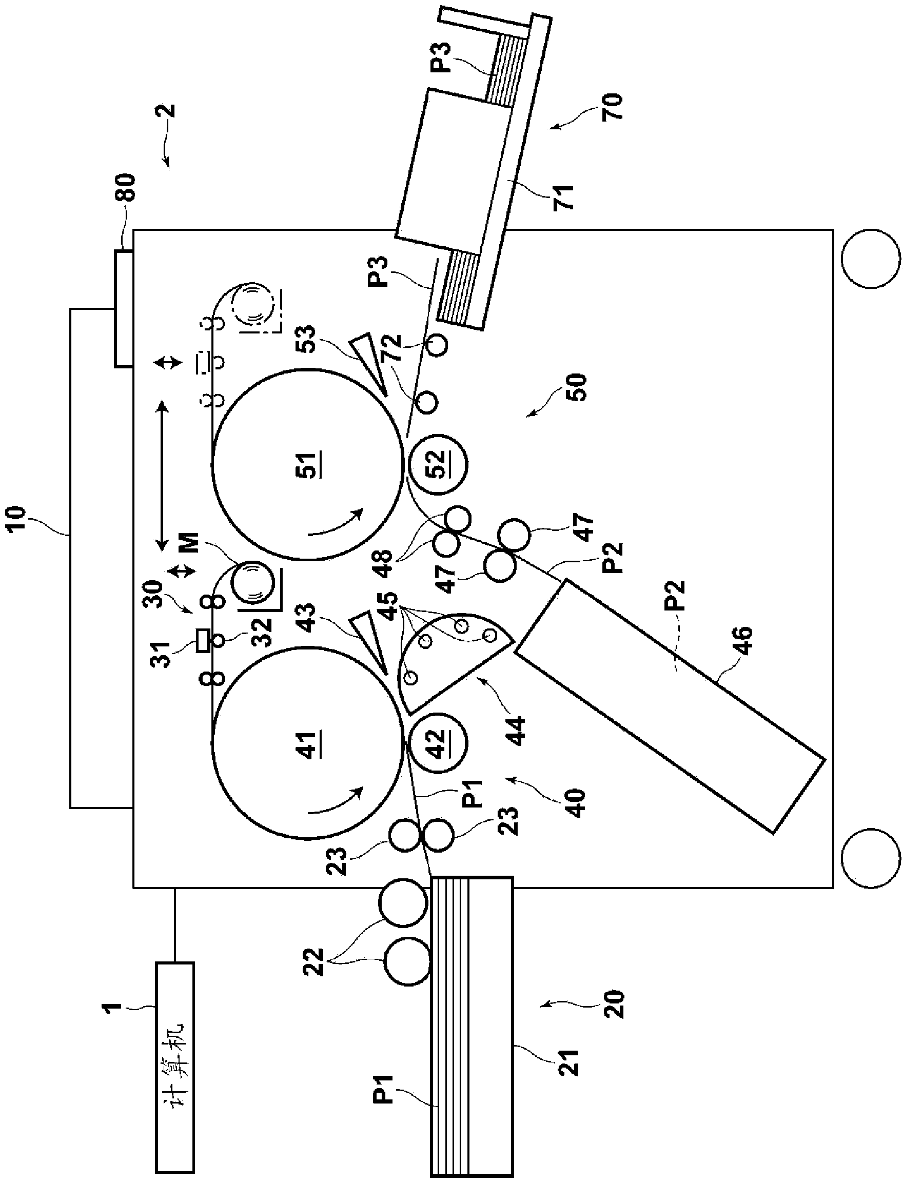
[0042] Next, a stencil printing system using an embodiment of the thermal head control device of the present invention will be described in detail with reference to the drawings. figure 1 This is a schematic diagram of the stencil printing system.

[0043] Such as figure 1 As shown, this stencil printing system includes a computer 1 and a stencil printing device 2. The computer 1 outputs image data for single-sided printing or double-sided printing. The stencil printing device 2 performs plate making based on the image data output from the computer 1. and stencil printing. This stencil printing system is characterized by a method of driving and controlling the thermal head in the stencil printing device 2 , and first, the overall structure of the stencil printing device 2 will be described.

[0044] Such as figure 1As shown, the stencil printing apparatus 2 includes: an image reading unit 10 that reads an image of an original document and outputs image data; image data ...


PUM


Abstract

Provided is a thermal head control device which carries out the driving control on a thermal head based on multi-valued data so as to control the diameter of a perforated hole and to prevent failure of perforating and offset. Heating time for perforating small holes on an orifice plate paper is controlled to be shorter than the eating time for perforating large holes. And, the temperature of a heating body for perforating small holes is lower than that for perforating large holes.

Description

technical field [0001] The invention relates to a thermal head control device for driving and controlling a thermal head, in which a plurality of heating elements for perforating stencil base paper are arranged. Background technique [0002] Conventionally, a thermal head device is used in a stencil printing system to perforate a stencil base paper by heating a plurality of heating elements based on image data output from a scanner, computer, or the like. [0003] In addition, as the above-mentioned stencil printing system, for example, a system for perforating a stencil base paper based on binary data has been proposed. [0004] However, in the case of perforating and performing stencil printing based on binary data, for example, when printing a full image (ベタタ like), such as Figure 19 As shown in the upper left figure of (when multi-valued is not performed), the overlapping portion increases due to dot gain (ドツトゲイン), so the color of the finished printed matter becomes d...

Claims


Application Information

Patent Timeline
Patent Type & Authority Patents(China)
IPC IPC(8): B41C1/055
Inventor 堀川直之
Owner RISO KAGAKU CORP
Why Eureka
Try Eureka