
Throwing hole orientator of bit hole rig and positioning method

A technology of roller cone drilling rig and locator, which is applied to earth-moving drilling, surveying, wellbore/well components, etc., can solve the problems of the roller cone drilling rig having no positioning function, laborious positioning, and time-consuming positioning, etc., and achieves simple structure and convenient use. , the effect of reducing labor intensity

Inactive Publication Date: 2013-09-25
郭昭华 +1
View PDF6 Cites 1 Cited by
  • Summary
  • Abstract
  • Description
  • Claims
  • Application Information

AI Technical Summary

Problems solved by technology

[0005] The technical problem to be solved by the present invention is: aiming at the lack of positioning function of the roller cone drilling machine in the prior art, which leads to the shortcomings of time-consuming, laborious and inaccurate positioning during use, a roller cone drilling machine throwing hole locator is provided, Also provided is a method for locating the throwing hole of the roller cone drill

Method used

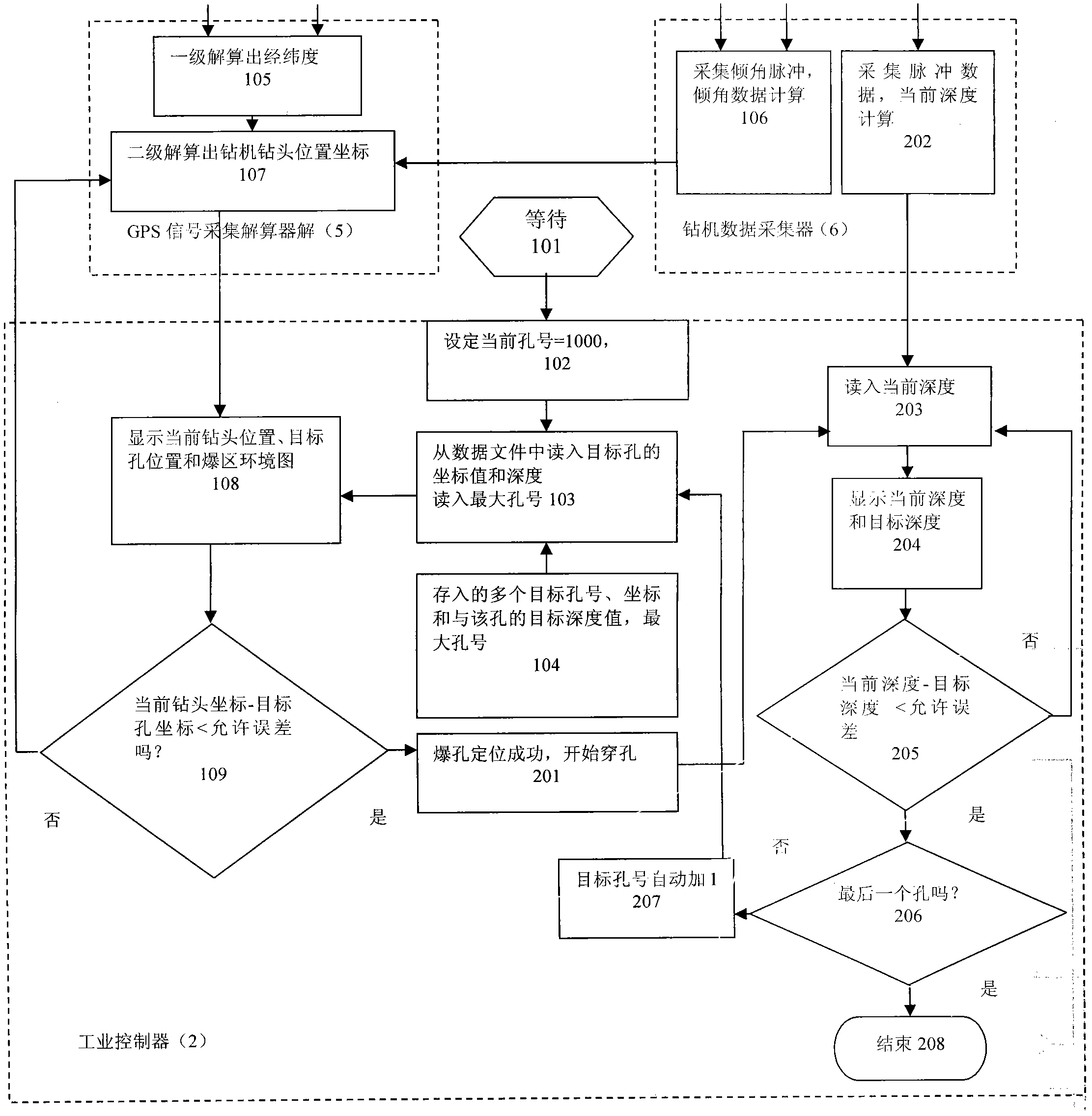

Image

  • Throwing hole orientator of bit hole rig and positioning method
  • Throwing hole orientator of bit hole rig and positioning method

Examples


Embodiment 1

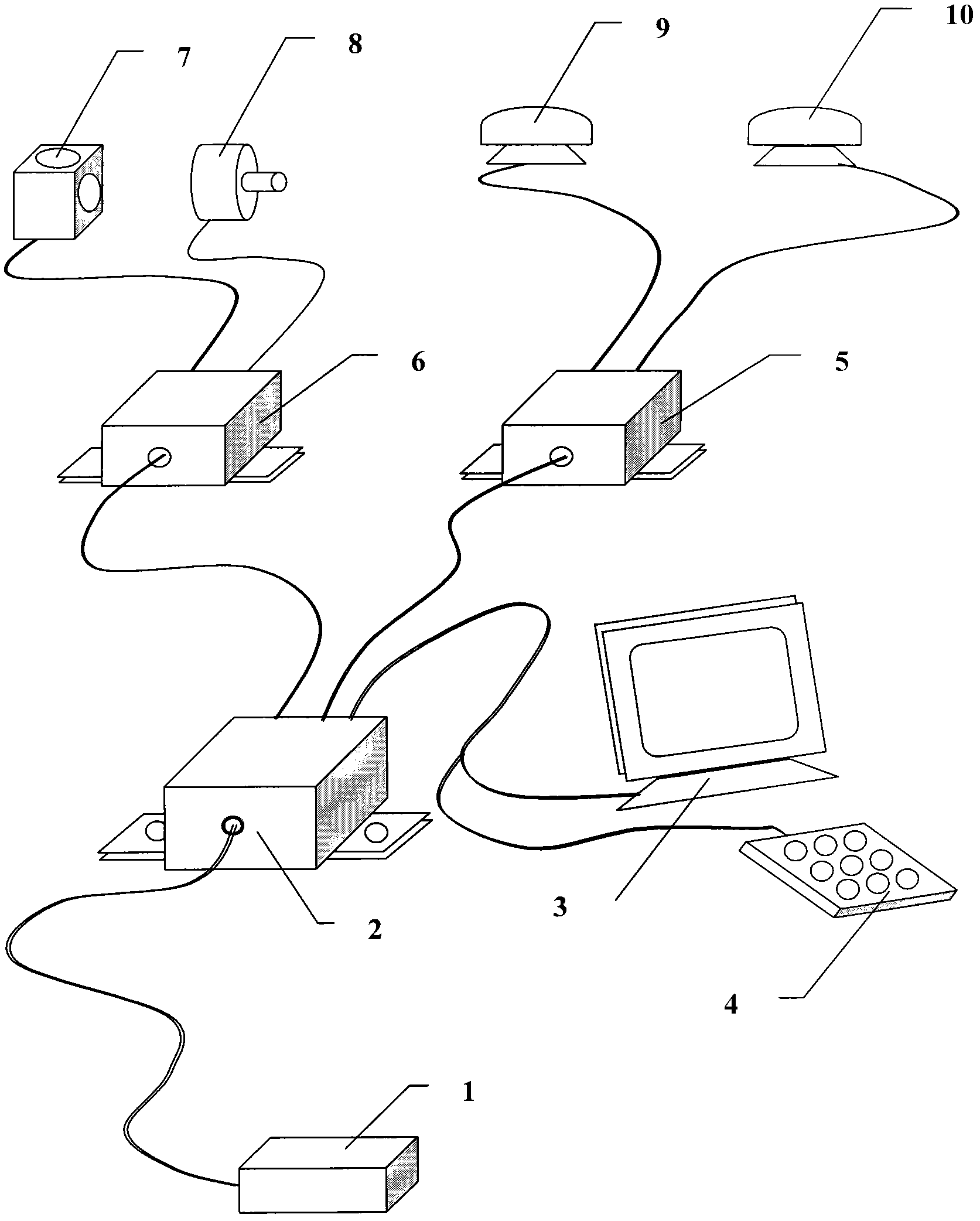
[0062] Such as figure 1 As shown, the roller drill throwing hole locator includes:

[0063] Two GPS antennas (9 and 10) are used to perceive the position of the drilling rig, and convert the received position information of the drilling rig into electrical signals and transmit them to the signal acquisition solver;

[0064] The signal acquisition solver 5 is used for real-time acquisition and buffering of the electrical signals from the two GPS antennas, and the electrical signals are resolved into the position coordinates of the centers of the two GPS antennas and sent to the controller;

[0065] Dual inclination sensors 7 are used to sense the inclination angle of the drilling rig, generate pulses related to the inclination angle, and transmit the inclination angle pulse data to the data collector;

[0066] The data collector 6 is used for collecting and buffering the inclination pulse data from the dual inclination sensors in real time, and transmitting the inclination pul...

Embodiment 2

[0093] Roller drill throw hole locators include:

[0094] Two GPS antennas 9 and 10 are used to sense the position of the drilling rig, convert the received position information of the drilling rig into electrical signals and send them to the signal acquisition solver;

[0095] Dual inclination sensors 7 are used to sense the inclination angle of the drilling rig, generate pulses related to the inclination angle, and transmit the inclination angle pulse data to the signal acquisition solver;

[0096] The signal acquisition solver 5 is used to collect and buffer the electrical signals from two GPS antennas in real time, and the inclination pulse data from the dual inclination sensors, and resolve the electrical signals and the inclination pulse data into drill bits. The position coordinates are transmitted to the controller;

[0097] The controller 2 is used to receive the drill bit position coordinates sent by the signal acquisition solver in real time, compare the drill bit ...


PUM


Abstract

The invention discloses a throwing hole orientator of a bit hole rig and a positioning method. The orientator comprises two GPS (global positioning system) antennae, a double-dip angle sensor, a signal acquisition solver and a controller, wherein the GPS antennae are used for sensing the position of a drilling machine and transmits the position information of the drilling machine to the signal acquisition solver; the double-dip angle sensor is used for sensing the dip angle of the drilling machine and transmits dip angle pulse data to the signal acquisition solver; the signal acquisition solver is used for collecting and caching electrical signals transmitted from the two GPS antennae in real time, and collecting and caching the dip angle pulse data transmitted from the double-dip angle sensor, the electrical signal and the dip angle pulse data are solved to the position coordinate of a drill, and the position coordinate of the drill is transmitted to the controller; the controller is used for receiving the position coordinate of the drill in real time; the position coordinate is compared with the position coordinate stored in the controller, of the target throwing hole; if errors are within a preset range, the throwing hole is positioned; and otherwise, the moved distance as required from the current drill to the target hole is calculated to output a mobile driving signal and positioning data. The orientator has the advantage of simple structure, is convenient to use and is reliable to work, and the position of the throwing hole can be accurately measured.

Description

technical field [0001] The invention relates to an instrument for locating a throwing hole of a roller drill, and also relates to a method for locating the throwing hole of a roller drill. Especially in open-pit mining, it is a positioning instrument and a positioning method that can automatically identify the position of the throwing hole as the roller cone drill moves, that is, when it advances, retreats and turns. Background technique [0002] At present, there is no throwing hole positioning equipment on the known roller cone drilling rigs. The conventional throwing hole positioning method is to rely on manual distance measurement. After placing stones on the ground, piling or painting to mark the position of the target hole, the driver's feeling is used to approach the mark and align the throwing. However, when using this method of operation, it is time-consuming, laborious, poor positioning accuracy and low efficiency, especially in the conditions of fog, rain, snow an...

Claims


Application Information

Patent Timeline
Patent Type & Authority Patents(China)
IPC IPC(8): E21B47/00E21B47/02E21B47/13E21B47/002E21B47/04
Inventor 郭昭华东青
Owner 郭昭华
Learn More