
Oil pan sealing structure

A technology of sealing structure and oil pan, which is applied in the direction of engine sealing, engine sealing device, engine components, etc., can solve the problems of limited compression and rebound ability of pressure resistance, time-consuming and labor-intensive cleaning work, and loss of sealing performance, etc., to achieve Improving durability, ensuring airtightness, and effective anti-aging effects

Inactive Publication Date: 2011-08-17
CHERY AUTOMOBILE CO LTD
View PDF4 Cites 2 Cited by
  • Summary
  • Abstract
  • Description
  • Claims
  • Application Information

AI Technical Summary

Problems solved by technology

In the prior art, the sealing method of the oil pan is mostly used to seal the oil pan. However, there are the following potential safety hazards in the sealing method: the quality requirements for the sealing surface are high, and a slight scratch on the sealing surface may cause oil leakage in the engine; In the assembly process of manual glue application, if the glue is not evenly applied, when these glue layers are squeezed, it is easy to cause blockage of the bolt holes or the oil return hole of the frame. Risk of oil seal being flushed out
Moreover, when the oil pan is sealed with glue, when the engine is repaired or the oil pan is replaced, the sealant on the frame or oil pan must be removed, which is time-consuming and laborious, and pollutes the environment
In view of the above problems, the prior art still adopts the rubber gasket sealing method, but due to the poor ability of the rubber material to withstand stress, after a period of use, under the combined action of pressure and temperature, the annular sealing gasket is easy to age or loosen. On the other hand, due to the limited pressure resistance and compression resilience of the rubber material, when the bolt is over-compressed, the gasket loses its original elastic deformation ability, resulting in poor sealing performance or loss of sealing performance of the gasket.

Method used


Image

  • Oil pan sealing structure
  • Oil pan sealing structure
  • Oil pan sealing structure

Examples


Embodiment Construction

[0016] The present invention will be described in detail below in conjunction with specific embodiments and accompanying drawings.

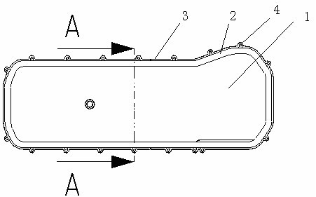
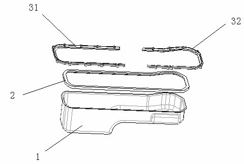
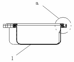
[0017] Such as figure 1 , 2 , 3, 4, the oil pan sealing structure of the present invention includes the flange surface 11 on the upper end of the oil pan body 1, the annular sealing gasket 2 for clamping the flange surface 11 of the oil pan 1, and the The annular reinforcing strip 3 under the annular sealing gasket 2, the radial section of the annular sealing gasket 2 is U-shaped, the annular reinforcing strip 3 is fixed to the crankcase frame, and the radial section of the annular reinforcing strip 3 is stepped. The area of ​​the upper half 21 of the radial section of the annular sealing gasket 2 is larger than the area of ​​the lower half 22 . The ring-shaped reinforcing slat 3 is a block structure, which is divided into two pieces 31 and 32 in this embodiment. The annular reinforcement strip 3 is fixed with the crankcase frame by the bolt ...


PUM


Abstract

The invention provides an oil pan sealing structure which has good tightness and is durable. The oil pan sealing structure comprises a flange face, a ring-shaped sealing washer and a ring-shaped reinforcing strip, wherein the flange face is at the upper end of an oil pan body, the ring-shaped sealing washer is used for clamping the flange face of the oil pan, and the ring-shaped reinforcing strip is arranged under the ring-shaped sealing washer; the radial cross section of the ring-shaped sealing washer is U-shaped; the ring-shaped reinforcing strip is fixed with the frame of a crank case; and the radial cross section of the ring-shaped reinforcing strip is step-shaped. The ring-shaped sealing washer with the U-shaped radial cross section is squeezed by the ring-shaped reinforcing strip with the step-shaped radial cross section, is fixed at the bottom of the frame of the crank case, so that all places of the flange face of the oil pan are effectively ensured to be clung to the ring-shaped sealing washer and the tightness between the oil pan body and the frame of the crank case is fully ensured; and as the ring-shaped sealing washer of the sealing structure has big force bearing area and uniformly bears force, the ring-shaped sealing washer can resist ageing more effectively and improves the durability of the oil pan sealing.

Description

technical field [0001] The invention belongs to the technical field of engines, and in particular relates to an oil pan sealing structure. Background technique [0002] The main function of the engine oil pan is to store and provide oil for the lubrication system, and together with the frame to form the crankcase, in order to prevent oil leakage, it is necessary to ensure a good seal between the oil pan and the frame. In the prior art, the sealing method of the oil pan is mostly used to seal the oil pan. However, there are the following potential safety hazards in the sealing method: the quality requirements for the sealing surface are high, and a slight scratch on the sealing surface may cause oil leakage in the engine; In the assembly process of manual glue application, if the glue is not evenly applied, when these glue layers are squeezed, it is easy to cause blockage of the bolt holes or the oil return hole of the frame. Risk of oil seal being blown out. Moreover, the ...

Claims


Application Information

Patent Timeline
IPC IPC(8): F02F11/00F16J15/06F01M11/00
Inventor 倪伟常绿付晓利
Owner CHERY AUTOMOBILE CO LTD
Features
  • Generate Ideas
  • Intellectual Property
  • Life Sciences
  • Materials
  • Tech Scout
  • Unparalleled Data Quality
  • Higher Quality Content
  • 60% Fewer Hallucinations
Learn More