Electric hydraulic control mechanism of novel hydraulic pressure transformer

A hydraulic transformer and electro-hydraulic control technology applied in the field of hydraulic components to achieve fast dynamic response, small moment of inertia and good control performance

Active Publication Date: 2011-08-17
BAOTOU SAIBEI MECHANICAL EQUIP CO LTD
View PDF5 Cites 8 Cited by
  • Summary
  • Abstract
  • Description
  • Claims
  • Application Information

AI Technical Summary

Problems solved by technology

[0003] The inventions of Achten University and Zhejiang University are mainly about how to ma...

Method used


Image

  • Electric hydraulic control mechanism of novel hydraulic pressure transformer
  • Electric hydraulic control mechanism of novel hydraulic pressure transformer
  • Electric hydraulic control mechanism of novel hydraulic pressure transformer

Examples


Embodiment Construction

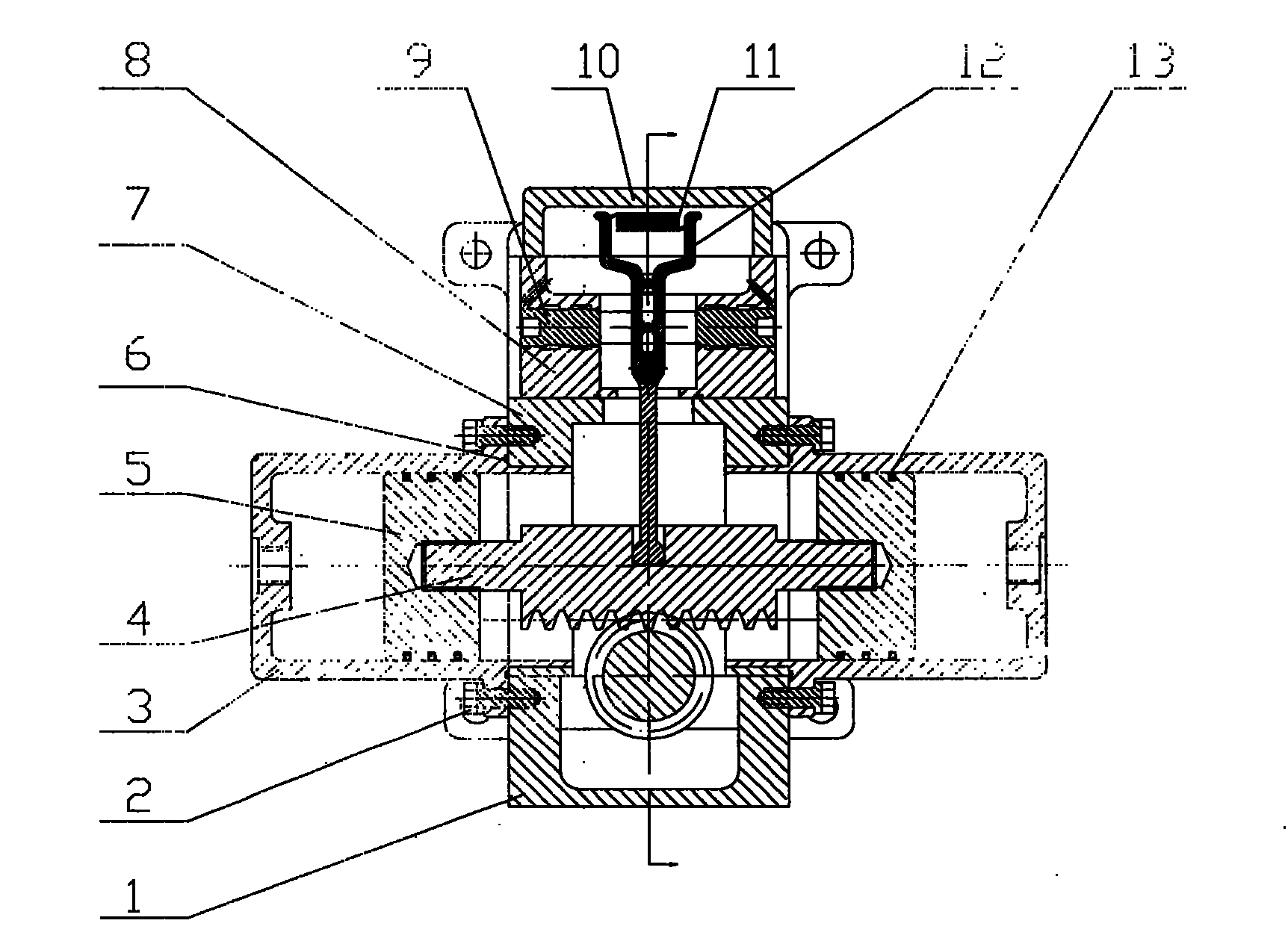
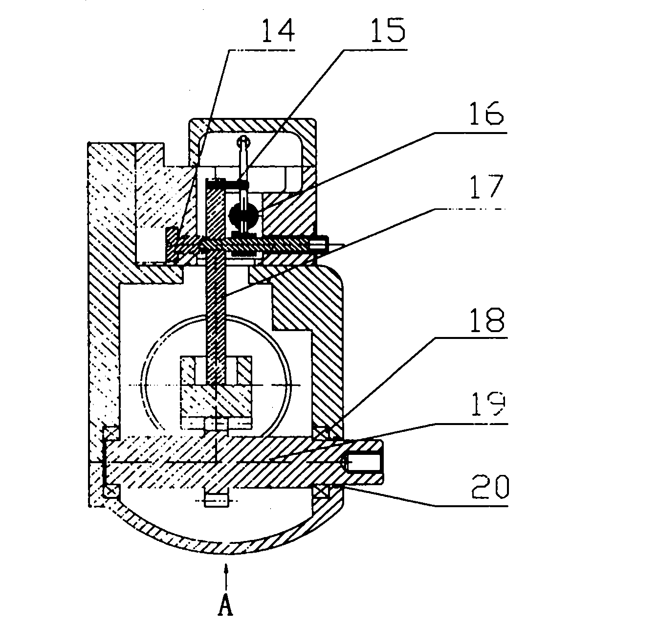
[0013] exist figure 1 with figure 2 Among them, the feedback spring (11) is connected to the shift fork (12), and the shift fork (12) is connected to the feedback lever (17) through the adjustment screw (16), and the feedback lever (17) has a pin (15) to form three Four-way solenoid valve body. The lower end of the feedback lever (17) is connected to the rack (4), the two ends of the rack (4) are connected to the piston (5) and the rack (4) is meshed with the gear shaft (19), and the gear shaft (19) is extended to connect to the distribution plate or swashplate.

[0014] The control principle of the electro-hydraulic control mechanism of the new hydraulic transformer is as follows:

[0015] When the three-position four-way solenoid valve is in the neutral position, the feedback spring (11) remains unchanged, the shift fork (12), the feedback lever (17), the rack (4), and the piston (5) do not move, and the gear shaft (19) If there is no rotation, the valve plate or the sw...


PUM


Abstract

The invention relates to an electric hydraulic servo mechanism applied to a hydraulic pressure transformer, which is formed by connecting a three-position four-way solenoid valve with a double-action rack oscillation hydraulic cylinder through an oil path. The inlet of the solenoid valve is connected with a hydraulic oil source and an oil tank respectively by oil paths. In the electric hydraulic servo mechanism, the solenoid valve controls a rack in the hydraulic cylinder to do reciprocating motion, so as to control the rotation of a gear by meshing, and a gear shaft extended out of the double-action rack oscillation hydraulic cylinder is combined with a flow distribution plate or an inclined plate so as to realize the purpose of controlling the control rotating angles of the hydraulic pressure transformer. In the double-action rack oscillation hydraulic cylinder, the rotary inertia is low, the dynamic response is rapid, and the control performance is good. For the electric hydraulic servo mechanism, the function of flexible control and regulation can be realized, the structure is compact and the volume is small.

Description

technical field [0001] The invention relates to hydraulic components, in particular to an electro-hydraulic control mechanism of a hydraulic transformer. Background technique [0002] At present, the invention patents and utility model patents on hydraulic transformers are basically about how to overcome the defects of throttling during the voltage transformation process of hydraulic transformers, including the invention patents and utility model patents proposed by domestic and foreign universities such as Achten University and Zhejiang University in China. The new patent enables the hydraulic transformer to fully realize its variable voltage range from zero to positive infinity. [0003] The inventions of Achten University and Zhejiang University are mainly about how to maximize the transformation ratio of hydraulic transformers, but rarely involve the control mechanism. Contents of the invention [0004] The purpose of the present invention is to propose a control mech...

Claims


Application Information

Patent Timeline
IPC IPC(8): F15B21/08F15B5/00
Inventor 魏超苑士华胡纪滨孟涛荆崇波李雪原尹旭峰彭增雄何融
Owner BAOTOU SAIBEI MECHANICAL EQUIP CO LTD
Why Eureka
Try Eureka