Fixture for three-coordinate measuring machine of blade and method for establishing measuring coordinate system

A three-coordinate measuring machine and a technology for measuring coordinate systems, which are applied to measuring devices, instruments, etc., can solve the problems of low measurement efficiency and difficult blade measurement coordinate systems, and achieve the effects of high positioning accuracy, reducing time and difficulty, and improving efficiency.

Inactive Publication Date: 2011-08-17
NORTHWESTERN POLYTECHNICAL UNIV
View PDF4 Cites 35 Cited by
  • Summary
  • Abstract
  • Description
  • Claims
  • Application Information

AI Technical Summary

Problems solved by technology

[0005] In order to overcome the shortcomings of difficult and low measurement efficiency in establishing a blade measurement coordinate system in the prior art, the present invention proposes a fixture for a blade three-coordinate measuring machine and a method for establishing a measurement coordinate system

Method used


Image

  • Fixture for three-coordinate measuring machine of blade and method for establishing measuring coordinate system
  • Fixture for three-coordinate measuring machine of blade and method for establishing measuring coordinate system
  • Fixture for three-coordinate measuring machine of blade and method for establishing measuring coordinate system

Examples


Embodiment 1

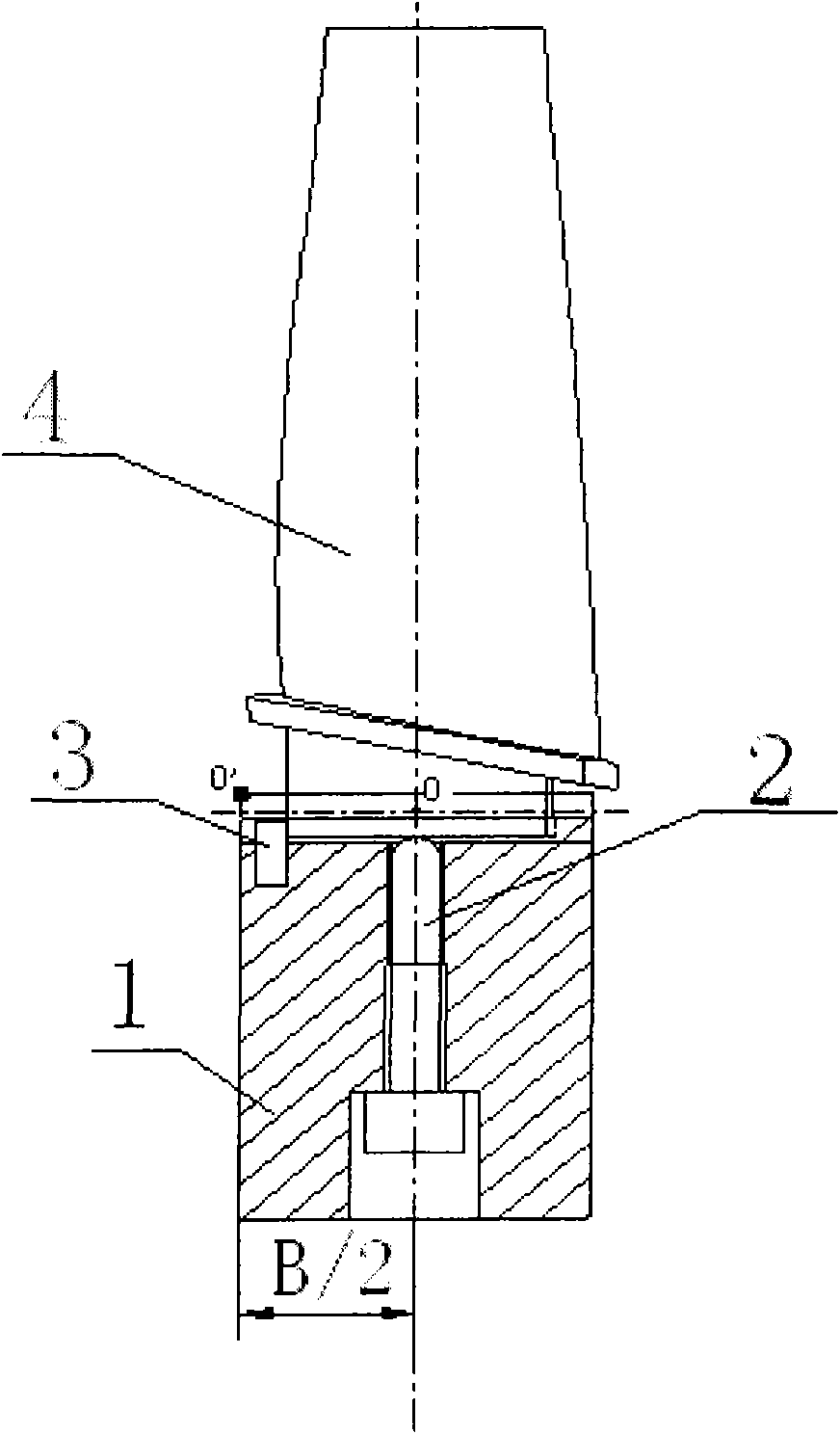
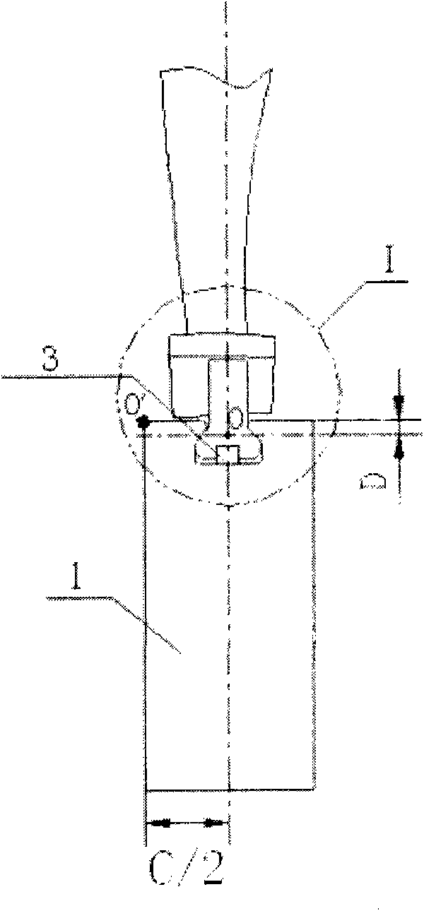
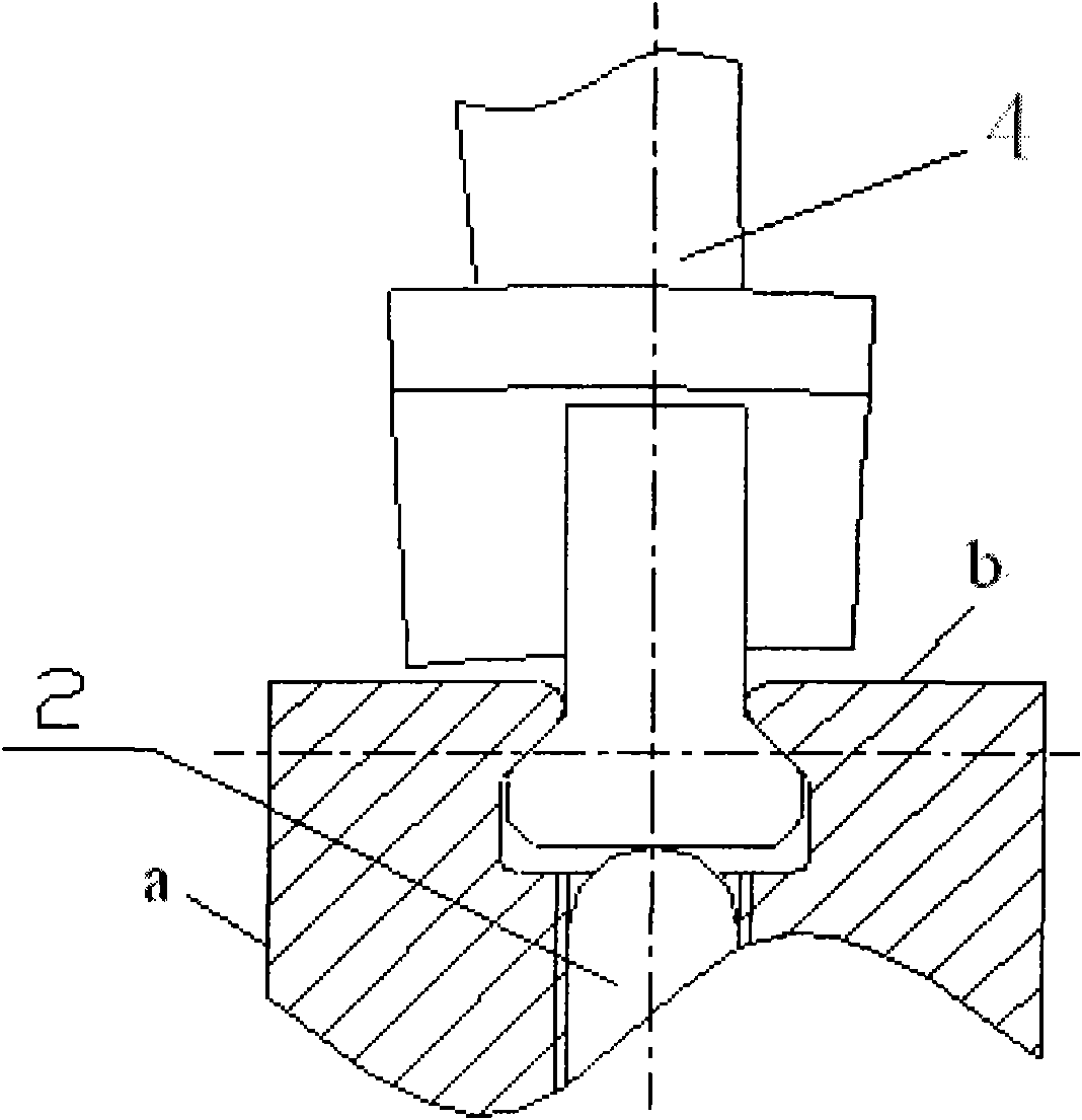
[0026] This embodiment is a fixture used for measuring blades of a certain type of aero-engine, including a fixture body 1 , jacking screws 2 and positioning pins 3 .

[0027] Such as figure 1 As shown, the clip body 1 of this embodiment is a cuboid, and its length is the same as that of the root of the blade. There is a V-shaped tongue and groove on the upper surface of the clamp body 1 . The groove walls on both sides of the V-shaped tenon groove are wedge-shaped surfaces, and the wedge-shaped surfaces completely coincide with the wedge-shaped surfaces of the blade root. The V-shaped tongue and groove are distributed along the length direction of the clip body and are located on the centerline of the width of the clip body 1 . There is a blind installation hole for the positioning pin shaft 3 at the groove bottom at any one end of the V-shaped tenon groove, and the center line of the blind installation hole is located in the longitudinal symmetrical plane of the V-shaped g...

Embodiment 2

[0041] This embodiment is a fixture used for measuring blades of a certain type of aero-engine, including a fixture body 1 , jacking screws 2 and positioning pins 3 .

[0042] Such as figure 1As shown, the clip body 1 of this embodiment is a cuboid, and its length is the same as that of the root of the blade. There is a V-shaped tongue and groove on the upper surface of the clamp body 1 . The groove walls on both sides of the V-shaped tenon groove are wedge-shaped surfaces, and the wedge-shaped surfaces completely coincide with the wedge-shaped surfaces of the blade root. The V-shaped tongue and groove are distributed along the length direction of the clip body and are located on the centerline of the width of the clip body 1 . There is a blind installation hole for the positioning pin shaft 3 at the groove bottom at any one end of the V-shaped tenon groove, and the center line of the blind installation hole is located in the longitudinal symmetrical plane of the V-shaped gr...


PUM


Abstract

The invention provides a fixture for a three-coordinate measuring machine of a blade and a method for establishing a measuring coordinate system. An upper surface of a fixture body is provided with a V-shaped tongue-and-groove, and a wedge-shaped surface of the V-shaped tongue-and-groove is completely coincided with a wedge-shaped surface of a blade tongue root. The V-shaped tongue-and-groove is positioned on a central line of a width of the fixture body. A set screw is positioned on a symmetric centre of a length and the width of the fixture body. When the measuring coordinate system of the fixture for the three-coordinate measuring machine of the blade is established, a coordinate plane is established through three points, a coordinate axis is established through projections of a connecting line of the two points on the coordinate plane and a coordinate origin point is determined by one point, and thereby the measuring coordinate system of the blade is fast and accurately established; moreover, the measuring coordinate system can be fast converted from the blade tongue root to the fixture body by using the rectangular fixture body so as to reduce time and difficulty of establishing the measuring coordinate system in the blade measuring process. The fixture of the invention has the advantages of simple structure, convenience for mounting and high locating precision, can be detached for multiple times without affecting the locating precision, can realize batch measurement of the blades and increases the blade measuring efficiency.

Description

technical field [0001] The invention relates to the technical field of engine blade measurement, in particular to a fixture for blade measurement. technical background [0002] The development of the modern aviation industry has higher and higher requirements for the technical performance of the engine. Various new blades have been designed. In order to ensure the quality of blades, different stages of blade manufacturing need to be measured, and the process runs through the entire stage from wool, machining to blade assembly. [0003] Blade detection is an important means to ensure the quality of blade manufacturing, but due to the existence of problems such as difficult positioning, it has always been a difficult point in the blade processing process, specifically manifested in: high measurement accuracy requirements; high measurement efficiency requirements; high measurement reliability requirements; The measurement positioning and the establishment of the measurement co...

Claims


Application Information

Patent Timeline
Patent Type & Authority Applications(China)
IPC IPC(8): G01B21/00
Inventor 蔺小军高春李宜明单晨伟王增强
Owner NORTHWESTERN POLYTECHNICAL UNIV
Why Eureka
Try Eureka