Optical detection clamp for thin-wall spiral groove type part

An optical detection and spiral groove technology, applied in the direction of using optical devices, measuring devices, instruments, etc., can solve the problem of non-blocking parts, and achieve the effects of avoiding reflection, stable positioning, and fast matching.

Active Publication Date: 2021-07-30
XIAN SPACE ENGINE CO LTD
View PDF8 Cites 0 Cited by
  • Summary
  • Abstract
  • Description
  • Claims
  • Application Information

AI Technical Summary

Problems solved by technology

[0004] The technical problem solved by the present invention is: to overcome the deficiencies of the prior art, to provide an optical detection fixture for thin-walled spiral groove parts, which solves the problem of the reference point in the batch measurement process of thin-walled spiral groove parts using three-dimensional structured light. Stable and reliable positioning is required, and the fixture itself does not block the parts

Method used


Image

  • Optical detection clamp for thin-wall spiral groove type part
  • Optical detection clamp for thin-wall spiral groove type part
  • Optical detection clamp for thin-wall spiral groove type part

Examples


Embodiment Construction

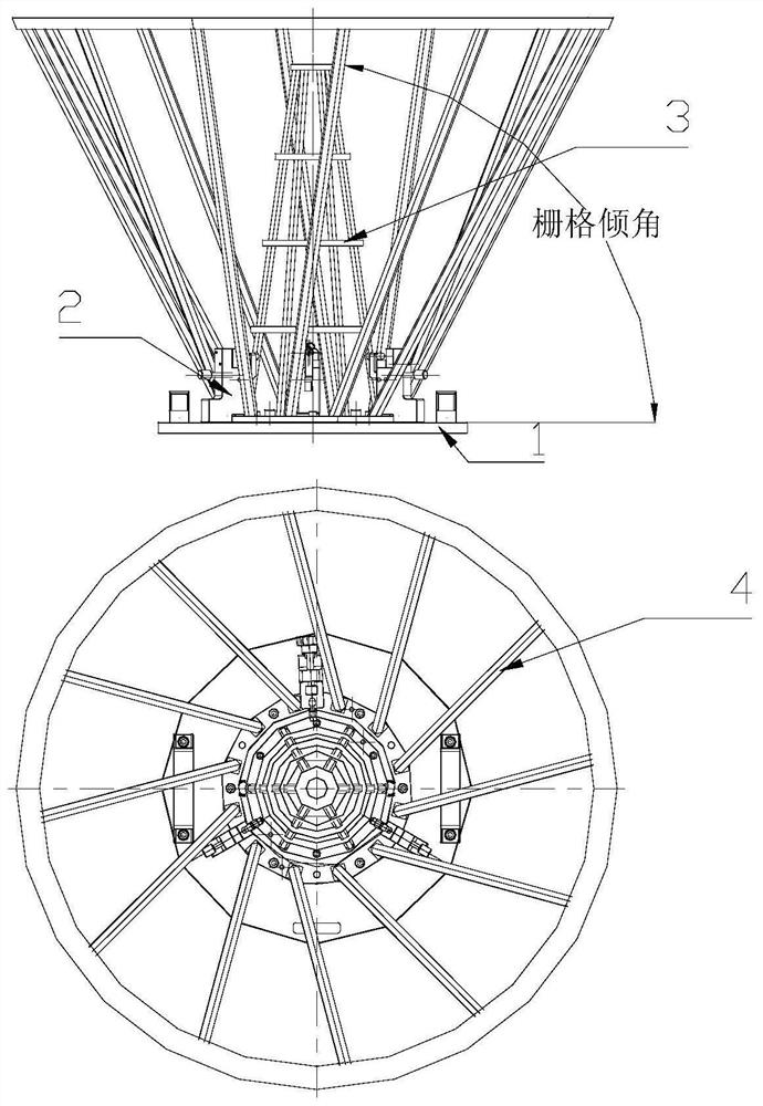
[0028] Refer to the attached Figure 1-6 , the present invention will be described in detail.

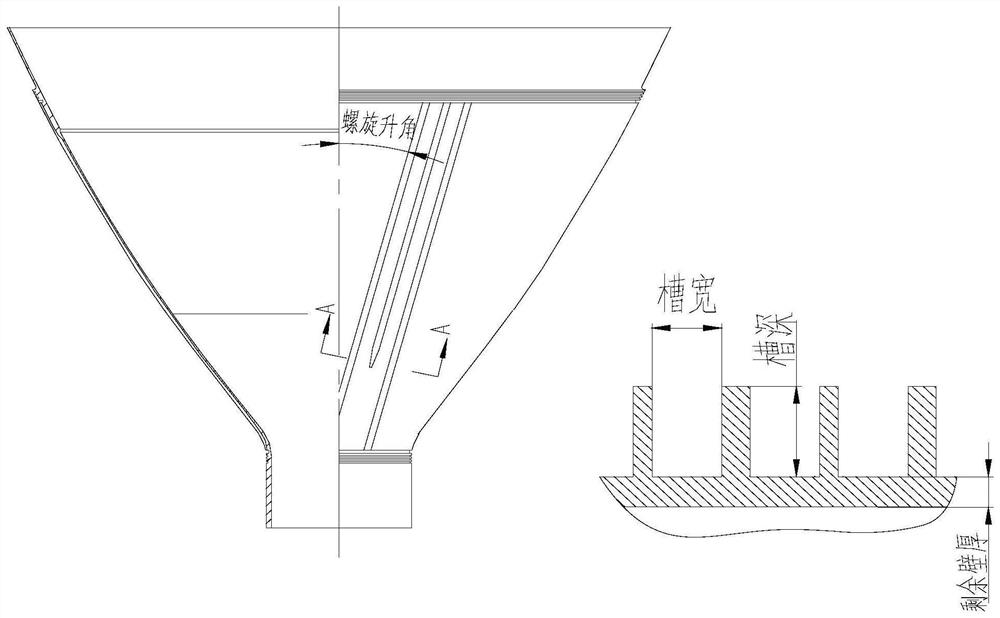
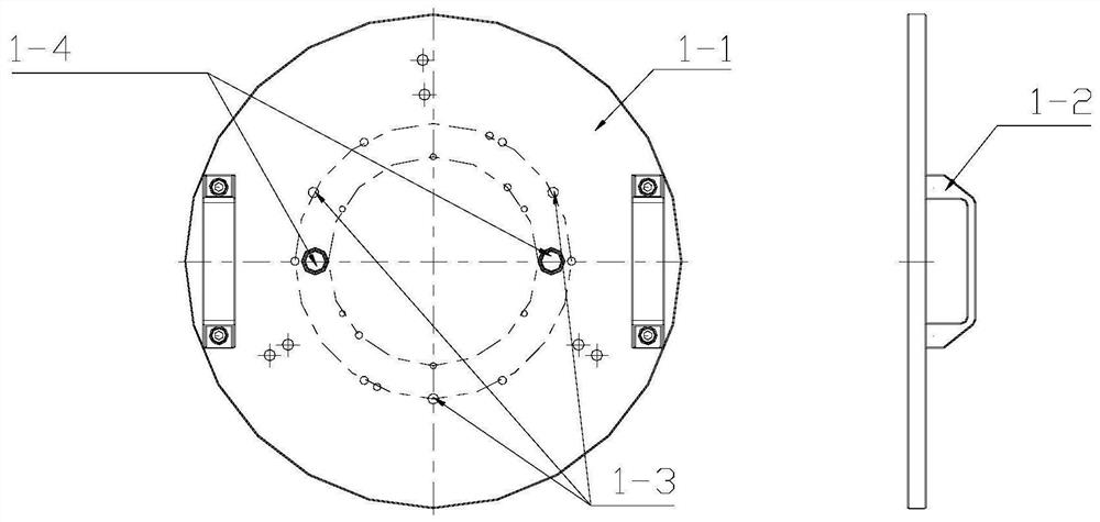
[0029] The invention provides an optical inspection fixture for thin-walled spiral groove parts, which includes a connection base 1, a clamping and positioning platform 2, an inner grid 3, an outer grid 4, and marking points. The connecting base 1 is composed of a metal disc 1-1, a handle 1-2, a connecting hole 1-3, and a positioning pin hole 1-4. The handle is connected with the metal disc 1-1 through bolts, and the connecting hole 1-3 is connected with the positioning pin The holes 1-4 are used to position and connect the fixture on the working turntable of the three-dimensional optical scanner; the clamping and positioning platform 2 is composed of three supporting blocks 2-1, and the supporting blocks 2-1 are connected to the metal disc 1-1 by bolts. Connection, the upper end of each support block 2-1 is provided with a groove, and the brass spacer 2-3 is placed in the groove; ...


PUM


Abstract

The invention provides an optical detection clamp for thin-wall spiral groove type parts. The optical detection clamp comprises a connecting base (1), a clamping positioning table (2), an inner grid (3), an outer grid (4) and mark points. The connecting base (1) is composed of a metal disc, a handle, a connecting hole and a positioning pin hole and used for carrying and fixing parts. The clamping positioning table (2) is composed of three evenly-distributed supporting blocks, and tightening screws and positioning screws are arranged on the supporting blocks and used for clamping and positioning parts. The inner grid (3) is of a hollow step-shaped frame structure, the outer grid (4) is of a conical frame structure, and mark points are fully distributed on the inner grid (3) and the outer grid (4) according to a certain rule, so that no less than three points in any direction in the breadth of the lens are ensured, and the space position is positioned in the measurement process. The fixture is applied to the process of scanning and measuring thin-wall spiral groove parts by structured light, and has the advantages of simplicity in clamping, no shielding, high positioning precision and the like.

Description

technical field [0001] The invention relates to an optical detection fixture for thin-walled spiral groove parts, belonging to the field of three-dimensional structured light scanning detection. Background technique [0002] Thin-walled spiral groove parts are widely used in liquid rocket engines. There are hundreds of spiral grooves on them. Among them, the groove width, groove depth, and remaining wall thickness are measured by traditional methods such as special calipers, which are time-consuming and labor-intensive. Coverage The reliability is low, and the three-dimensional structured light method can be used to achieve rapid measurement of this type of parts. [0003] When performing three-dimensional structured light measurement on large-size, high-precision parts, it is necessary to use common reference point splicing technology to improve measurement accuracy. At present, the common practice in the industry is to directly paste the points on the parts. This method i...

Claims


Application Information

Patent Timeline
Patent Type & Authority Applications(China)
IPC IPC(8): G01B11/00
CPCG01B11/00
Inventor 李波李业栋刘林王卿杨培剑李强何小虎
Owner XIAN SPACE ENGINE CO LTD
Why Eureka
Try Eureka