Liquid crystal displaying device, liquid crystal displaying panel and driving method

A technology of a display device and a driving method, which is applied in static indicators, nonlinear optics, optics, etc., can solve problems such as light leakage, damage, and damaged parts, and achieve the effect of improving the light-shielding effect

Active Publication Date: 2011-08-17
INNOLUX CORP
View PDF3 Cites 7 Cited by
  • Summary
  • Abstract
  • Description
  • Claims
  • Application Information

AI Technical Summary

Problems solved by technology

[0006] However, the first known technology still has the problem of light leakage. When the light absorption value or optical density (Optical Density, OD) of the color filter layer 221 is insufficient, the light will still be emitted through the color filter layer 221, so that the light-shielding area Z2 light leakage
[0007] In addition, the second known technology is easy to form an electrostatic discharge structure with the metal wi

Method used


Image

  • Liquid crystal displaying device, liquid crystal displaying panel and driving method
  • Liquid crystal displaying device, liquid crystal displaying panel and driving method
  • Liquid crystal displaying device, liquid crystal displaying panel and driving method

Examples


no. 1 example

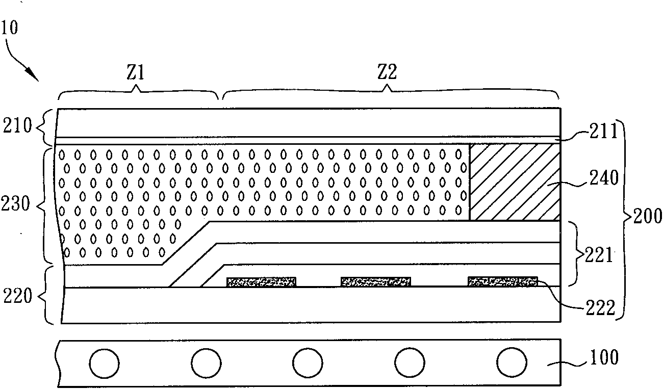
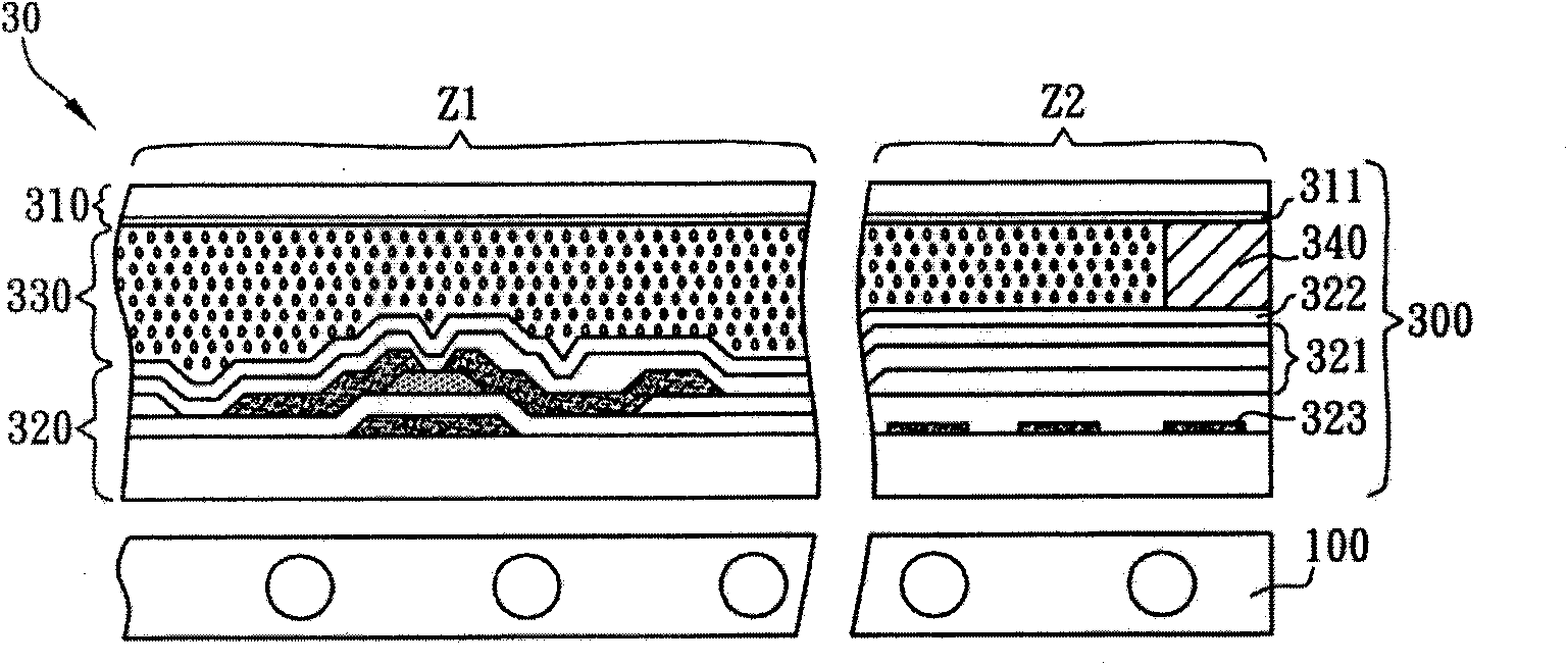
[0058] Please refer to Figure 2A and Figure 2B As shown, the liquid crystal display device 30 according to the first embodiment of the present invention includes a backlight module 100 and a liquid crystal display panel 300 . The backlight module 100 is, for example, a direct type backlight module or a side-edge type backlight module. In this embodiment, the backlight module 100 is described by taking a direct-type backlight module as an example, but it is not intended to limit the scope of rights of the present invention.

[0059] The liquid crystal display panel 300 is, for example, an in-plane switching (IPS) type liquid crystal display panel, a multi-domain vertical alignment (MVA) type liquid crystal display panel, a twisted nematic (TN) type liquid crystal display panel, a color filter on a thin film transistor array ( COA) type liquid crystal display panel or transflective liquid crystal display panel. In this embodiment, the COA type liquid crystal display panel w...

no. 2 example

[0083] The second embodiment of the present invention, such as Figure 8 The difference between the liquid crystal display panel 500 of the illustrated liquid crystal display device 50 and the liquid crystal display panel 300 of the first embodiment is that the first substrate 510 and the second substrate 520 are, for example, a combination of a color filter substrate and a thin film transistor substrate. This will be described by taking the combination of the first substrate 510 as a thin film transistor substrate and the second substrate 520 as a color filter substrate as an example.

[0084] Similar to the first embodiment, the second substrate 520 has a first light shielding layer 521 and a second light shielding layer 522 thereon. The first light shielding layer 521 is, for example, a color filter layer or an organic insulating layer, and the second light shielding layer 522 is, for example, a second electrode layer or a metal layer.

[0085] Therefore, similarly, the fi...


PUM


Abstract

The invention provides a liquid crystal displaying device that comprises a backlight module and a liquid crystal displaying panel that is arranged at one side of the backlight module, wherein the liquid crystal displaying panel comprises a first substrate, a second substrate and a liquid crystal layer that is arranged between the first substrate and the second substrate; the second substrate is arranged opposite to the first substrate; the first substrate and the second substrate commonly form a displaying area and a light shielding area that is arranged around the displaying area; the first substrate in the light shielding area is provided with a first electrode layer; and the second substrate is provided with a first light shielding layer and a second light shielding layer. The invention also discloses a driving method that corresponds to the device.

Description

technical field [0001] The present invention relates to a method for reducing light leakage in a light-shielding area, in particular to a method for reducing light leakage in a light-shielding area used in a liquid crystal display device and a liquid crystal display panel. Background technique [0002] With the gradual maturity of the liquid crystal display (Liquid Crystal Display, LCD) technology, it has gradually replaced the traditional display technology using a cathode ray tube (CRT), and is widely used in various electronic products. Among them, liquid crystal display panels can be further classified into In Plane Switching (IPS) type, Multi-domain Vertical Alignment (MVA) type, Twist Nematic (TN) type, and color filters in Thin film transistor array (Color filter On Array, COA) type or transflective (Transflective) and so on. Herein, a COA type liquid crystal display panel will be used as an example for illustration. However, those skilled in the art should know that...

Claims


Application Information

Patent Timeline
IPC IPC(8): G02F1/133G02F1/1335
Inventor 卢嵘男萧富元
Owner INNOLUX CORP
Why Eureka
Try Eureka