
Upright type computer host machine

A computer mainframe and upright technology, applied in the direction of electrical digital data processing, instruments, digital data processing components, etc., can solve the problems of unable to perform normal air supply and heat dissipation operations, unconditional use, etc.

Inactive Publication Date: 2011-08-17
陈亮合
View PDF5 Cites 1 Cited by
  • Summary
  • Abstract
  • Description
  • Claims
  • Application Information

AI Technical Summary

Problems solved by technology

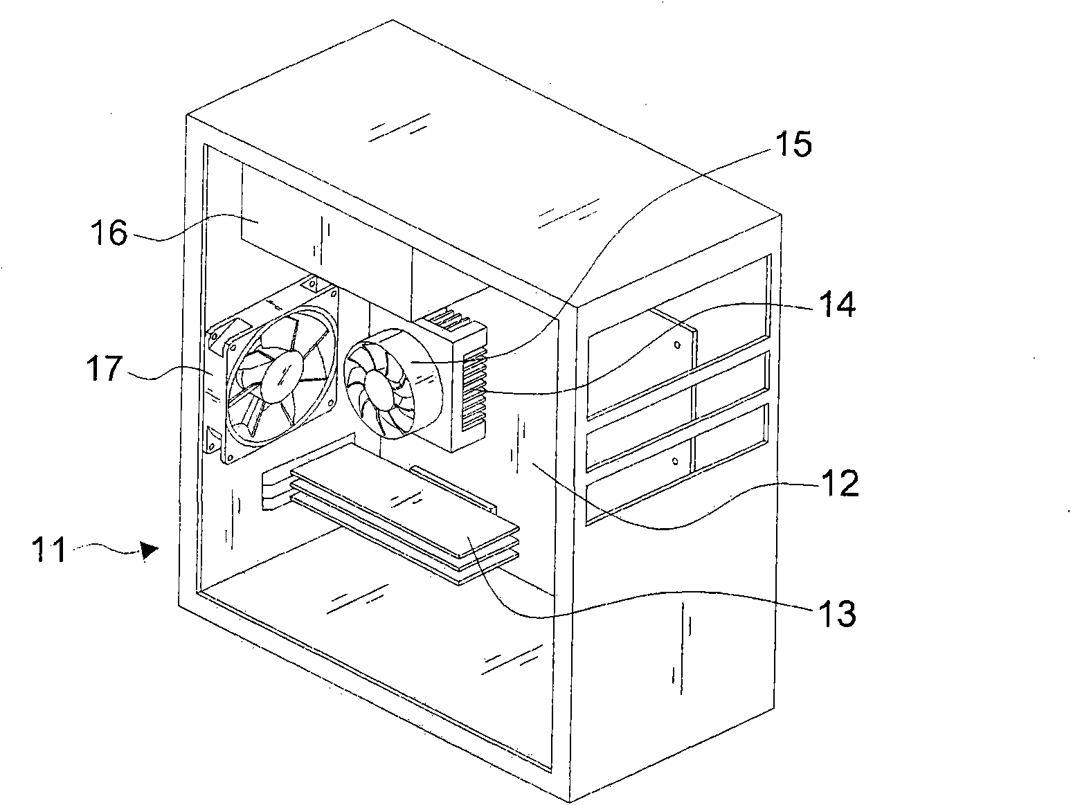
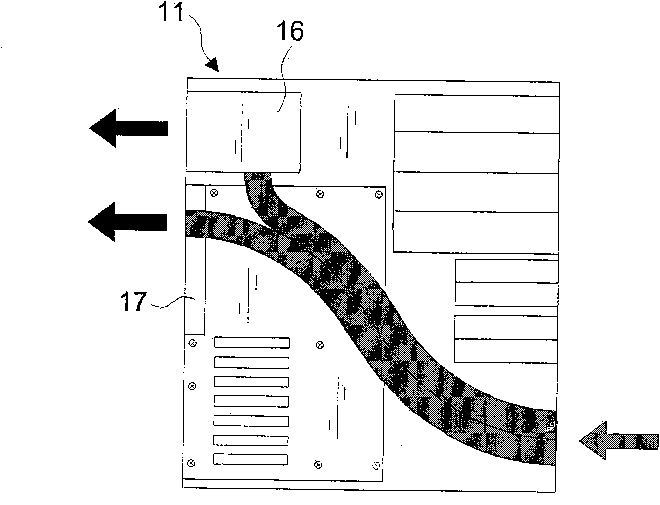
[0015] The most serious thing is that the advancement of chip manufacturing technology has enabled many expansion cards with low power consumption, such as communication, network, audio, display, etc., to be integrated on the motherboard one by one. As a computer with the appeal of streamlining, if the performance of the expansion card is not significantly different from that of the streamlined computer, the product will disappear from the market due to loss of value, especially products such as display and graphics cards. Because the power consumption is no less than that of the computing processor on the motherboard, it has not been completely replaced by the compact computer. Therefore, the requirements for the installation conditions of the radiator for products such as display and graphics cards should be compared with those of the computing processor. Equally, the expansion slots on the mainboard today still follow a distance of every two centimeters, plus the current expansion card, only the fan suction port becomes a single-oriented plug pin, and the mainboard 13 is like Figure 1A As shown, it is set and installed at the bottom of the chassis. If you directly plug in the expansion cards one by one, even a thin fan will have problems. There is no room for improvement due to the use of expansion components that are visibly different from thin PCs

Method used


Image

  • Upright type computer host machine
  • Upright type computer host machine
  • Upright type computer host machine

Examples


Embodiment Construction

[0099] First, see Figure 9A , Figure 9B , Figure 9C As shown, the main structure of the vertical computer mainframe 20 of the present invention includes:

[0100] A vertical bottom box 30 at least includes a ㄩ-shaped body formed by the bottom surface 31, the front frame body 32, and the rear frame body 33, which can be integrally formed according to requirements, or can be connected and assembled; it can be combined with the existing vertical bottom box The difference between the boxes is that the left and right sides are open for assembly without any frame obstruction, and the assembly height H of the vertical bottom box 30 is greater than but not more than 2.1 times the front width W, that is, 2.1W≥ H>W, and the length L is not more than 2.5 times of the front width W, so as to maintain the best placement of the center of gravity of the vertical chassis.

[0101] A receiving member 34 is located in the middle section of the width surface W of the vertical bottom box 30...


PUM


Abstract

The invention relates to an upright type computer host machine, which comprises an upright bottom chamber, a loading component and a first electric connecting port hole, wherein the upright bottom chamber comprises a U-shaped body formed by a bottom and front and back frame bodies; the loading component is arranged on the middle section of the width surface of the upright bottom chamber and is connected to the inner side of the front and back frame bodies, so as to form an upright combined plate and provide a longitudinal upright fixing position of a reserved plate component; a longitudinal matching line is formed by connecting the combined plate as the loading component from the front frame body to the back frame body, so as to divide the lateral width surface of the upright bottom chamber into a first assembling chamber with an opening towards left side and a second assembling chamber with the opening towards right side; and the first electric connecting port hole is uprightly arranged on the back frame body close to the loading component and is positioned in the first assembling chamber. The length and height of the upright type computer host machine can be properly reduced, so as to increase the loading volume of a case, increase the convenience for installing and upgrading and increase the radiation efficiency by a separated air field.

Description

technical field [0001] The present invention relates to an upright computer mainframe, in particular to a bottom box of an upright computer system mainframe, which is set so that a mainboard can be vertically fixed at the middle section of the width surface to form an assembly compartment, a wind field Divided tower computer mainframe. Background technique [0002] The effect of Moore's Law shows that the performance of products with chip manufacturing technology must be directly proportional to power consumption and inversely proportional to temperature rise. Therefore, the power consumption of products at the same stage is equal to the level of utility. The mainframes of systems such as computers, servers, and game machines formed by products, for the production of chip radiators, in addition to the requirement of blowing the front to the heat source (for the production of radiators, the inventor has previously proposed several items on how to use the wind force Concentra...

Claims


Application Information

Patent Timeline
IPC IPC(8): G06F1/16G06F1/20
Inventor 陈亮合
Owner 陈亮合
Learn More