
High-efficiency and high-power factor power circuit for permanent magnet synchronous driver

A technology of power factor and power circuit, applied in high-efficiency power electronic conversion, output power conversion device, electrical components, etc., can solve the problems of power grid pollution, low price, serious problems, etc., and achieve the effect of improving power factor

Inactive Publication Date: 2013-04-10
北京运通恒昌科技集团有限公司
View PDF3 Cites 0 Cited by
  • Summary
  • Abstract
  • Description
  • Claims
  • Application Information

AI Technical Summary

Problems solved by technology

The power supply circuit of the existing permanent magnet synchronous drive adopts a combination of rectifier bridge and filter circuit. This method is low in price, but it pollutes the power grid very seriously, and the power factor is very low, generally around 0.6.
Since the rectifier and capacitor filter circuit is a combination of nonlinear elements and energy storage elements, although the input is a sinusoidal AC voltage, the input current waveform is a discontinuous waveform with high-order harmonics, which affects the input power. factor
The easiest way to improve the power factor is to use passive correction and connect an inductance-capacitor filter to the rectified output. This method can make the power factor reach about 0.85, but it can only suppress certain harmonics, and there are certain limitations. The size and price limit the application in the drive

Method used

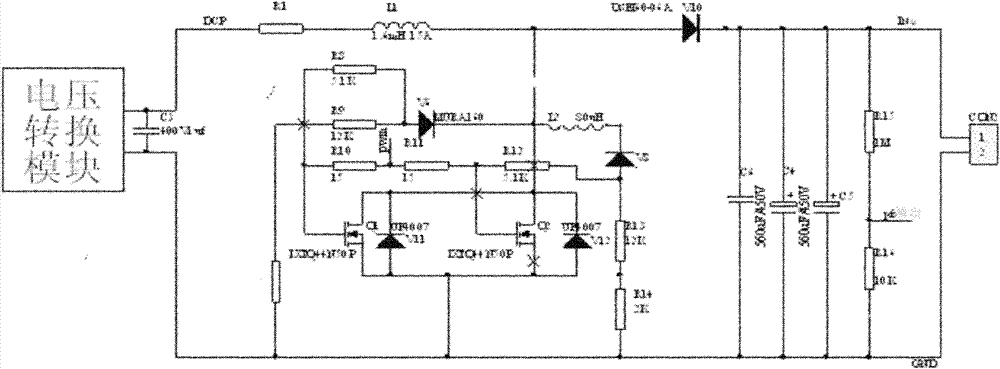
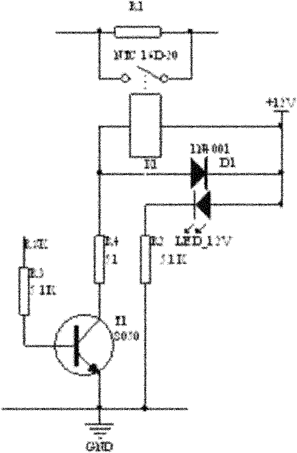
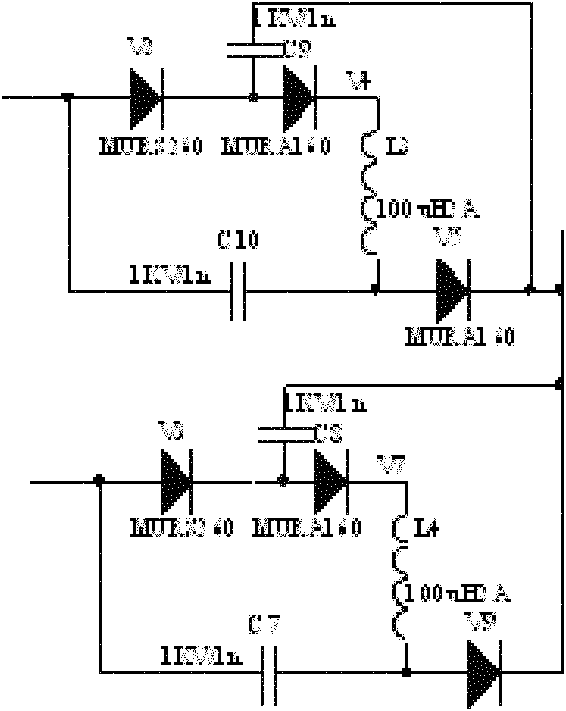

Image

  • High-efficiency and high-power factor power circuit for permanent magnet synchronous driver
  • High-efficiency and high-power factor power circuit for permanent magnet synchronous driver
  • High-efficiency and high-power factor power circuit for permanent magnet synchronous driver

Examples


Embodiment Construction

[0015] The present invention will be described in detail below with reference to the accompanying drawings and examples.

[0016] Most inverter power supplies use a combination of rectifier bridge and filter circuit. This method is low in price, but it pollutes the power grid very seriously, and the power factor is very low, generally around 0.6. At the same time, since the rectifier and capacitor filter circuit is a combination of nonlinear elements and energy storage elements, although the input is a sinusoidal AC voltage, the input current waveform is a discontinuous waveform with high-order harmonics, which affects the input terminal power factor. Existing passive rectifiers are used to improve the power factor by connecting the rectified output with an inductance-capacitor filter. This method can make the power factor reach about 0.85, but it can only suppress certain harmonics and has certain limitations. The present invention adopts active power factor correction to ob...


PUM


Abstract

The invention discloses a high-efficiency and high-power factor power circuit for a permanent magnet synchronous driver. The high-efficiency and high-power factor power circuit comprises a voltage conversion module and a power factor correction module, wherein the voltage conversion module is used for converting received AC voltage into DC voltage; and the power factor correction module is used for increasing a power factor of the power circuit. The high-efficiency and high-power factor power circuit is obtained by adopting active power factor correction; a boosting conversion device is arranged between a rectifier bridge and a filtering capacitor; control is driven by a dedicated integrated circuit (IC); an additional circuit shapes input current and controls output voltage; therefore, the power factor is well controlled, and simultaneously, the output voltage is ensured to be stable and unchanged along with input voltage.

Description

technical field [0001] The invention relates to the technical field of energy saving, in particular to a high power factor power supply circuit for a permanent magnet synchronous drive. Background technique [0002] With the development of industrial automation technology, motor drives are used more and more widely. Because of their excellent speed regulation performance and obvious energy-saving effect, they are used more and more widely. The power supply circuit of the existing permanent magnet synchronous driver adopts a combination of rectifier bridge and filter circuit. This method is low in price, but it pollutes the power grid very seriously, and the power factor is very low, generally around 0.6. Since the rectifier and capacitor filter circuit is a combination of nonlinear elements and energy storage elements, although the input is a sinusoidal AC voltage, the input current waveform is a discontinuous waveform with high-order harmonics, which affects the input power...

Claims


Application Information

Patent Timeline
IPC IPC(8): H02M1/42H02M1/14H02M1/32
CPCY02B70/126Y02B70/10
Inventor 李保民赵晓光
Owner 北京运通恒昌科技集团有限公司
Learn More