Automatic optical module send-receive integrated test system

An automated testing, optical module technology, applied in transmission monitoring/testing/fault measurement systems, transmission systems, electromagnetic wave transmission systems, etc., can solve the problems of time-consuming, low test efficiency, uncertainty errors, etc., to reduce the impact of human factors , Improve test efficiency, easy to implement effect

Inactive Publication Date: 2011-08-17
DONGGUAN MENTECH OPTICAL & MAGNETIC CO LTD
View PDF2 Cites 24 Cited by
  • Summary
  • Abstract
  • Description
  • Claims
  • Application Information

AI Technical Summary

Problems solved by technology

During the whole test process, the testers move frequently, the test efficiency is low, it is very time-consuming, and the test results also bring uncertain errors due to the individual differences of the testers.

Method used


Image

  • Automatic optical module send-receive integrated test system
  • Automatic optical module send-receive integrated test system
  • Automatic optical module send-receive integrated test system

Examples


Embodiment Construction

[0010] In order to facilitate the understanding of those skilled in the art, the structural principle of the present invention will be further described in detail below in conjunction with specific embodiments and accompanying drawings:

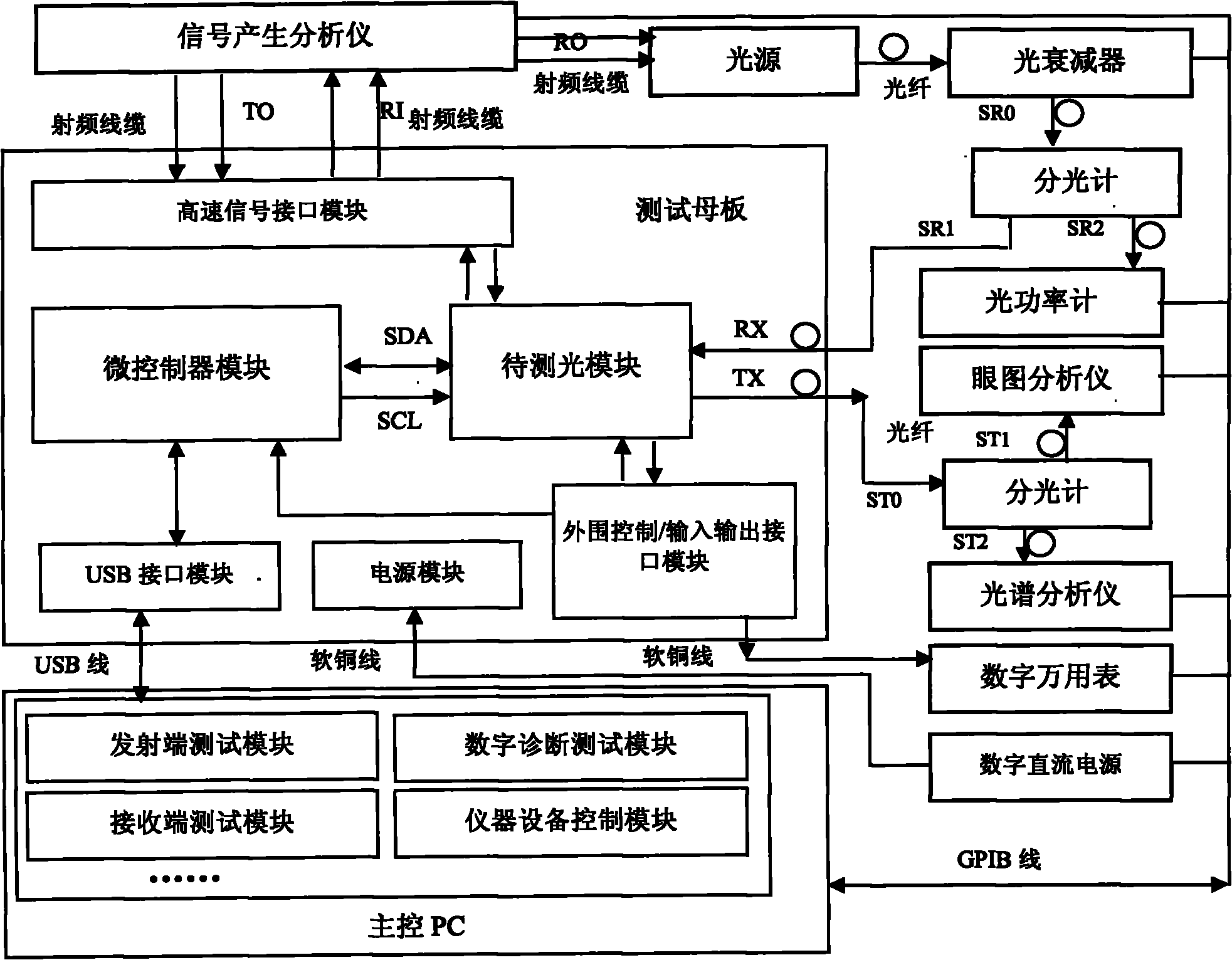
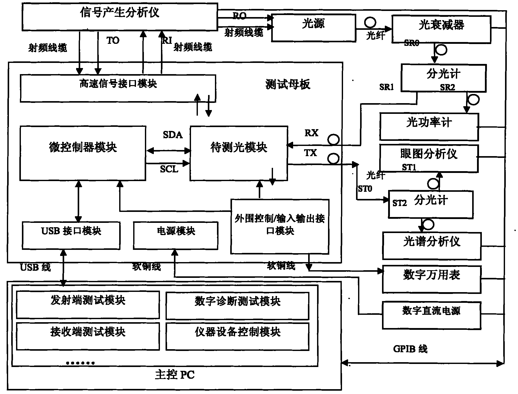
[0011] Such as figure 1 As shown, an automatic test system for optical transceiver transceiver is designed. It includes testing equipment and testing software, and the testing equipment includes a signal generation analyzer, a light source, an optical attenuator, a spectrometer, an optical power meter, an eye diagram analyzer, a spectrum analyzer, a digital multimeter, a digital DC power supply, a test mother board and the main control PC, the signal generating analyzer is connected to the light source through a radio frequency cable, the light output by the light source is transmitted to the optical attenuator through the optical fiber, and the light output by the optical attenuator is connected to the spectrometer through the optical fiber,...


PUM


Abstract

The invention discloses an automatic optical module send-receive integrated test system, comprising a test device and test software. The test device comprises a signal generating analysis meter, an optical source, an optical attenuator, a spectrometer, an optical power meter, an eye pattern analysis meter, a spectrum analyzer, a digital multimeter, a digital direct-current power supply, an optical module to be tested, a test mother board, a master control PC and joints among the devices; and the test software comprises a communication interface module, an instrument control module, a sending terminal test module, a receiving terminal test module, a digital diagnosis test module, a test process control module, a test specification download module and a data storage module. The automatic optical module send-receive integrated test system has the advantages of effectively improving efficiency, maintaining consistency and accuracy of the test process and reducing influence from manual operation in the test process.

Description

technical field [0001] The invention relates to the field of optical module testing, in particular to an automatic testing system integrating optical module sending and receiving. Background technique [0002] At present, in the optical module test, the tester needs to manually switch between different test platforms. At the same time, the tester needs to manually refresh (or switch) the data analysis software module of the eye diagram analyzer during the test process of the transmitter. The test process of the receiver needs The tester manually adjusts the optical attenuator to change the incident optical power at the receiving end of the optical module to be tested. During the whole test process, the testers move frequently, the test efficiency is low, and it is very time-consuming. The test results also bring uncertainty errors due to the individual differences of the testers. Contents of the invention [0003] The problem to be solved by the present invention is to pr...

Claims


Application Information

Patent Timeline
Patent Type & Authority Applications(China)
IPC IPC(8): H04B10/08H04B10/07
Inventor 杨先进周勇
Owner DONGGUAN MENTECH OPTICAL & MAGNETIC CO LTD
Why Eureka
Try Eureka