
Selective non-catalytic reduction (SNCR) denitration multi-nozzle long-gun injector
A multi-nozzle and injector technology, which is applied in chemical instruments and methods, dispersed particle separation, separation methods, etc., can solve the problems of unstable performance and low denitrification efficiency, and achieve improved coverage, improved denitrification efficiency, and increased compatibility. sexual effect
- Summary
- Abstract
- Description
- Claims
- Application Information
AI Technical Summary
Problems solved by technology
Method used
Image

Examples
Embodiment Construction
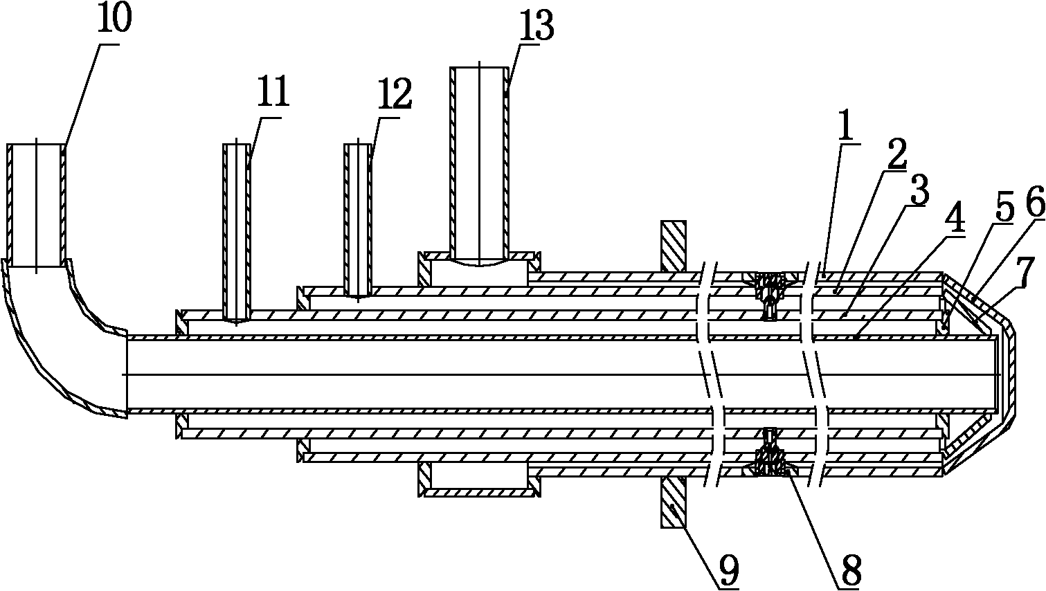
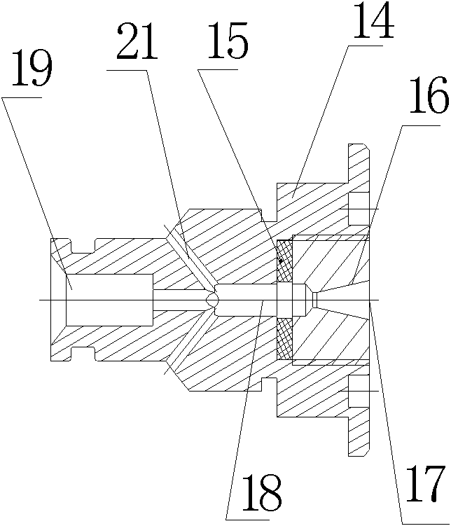
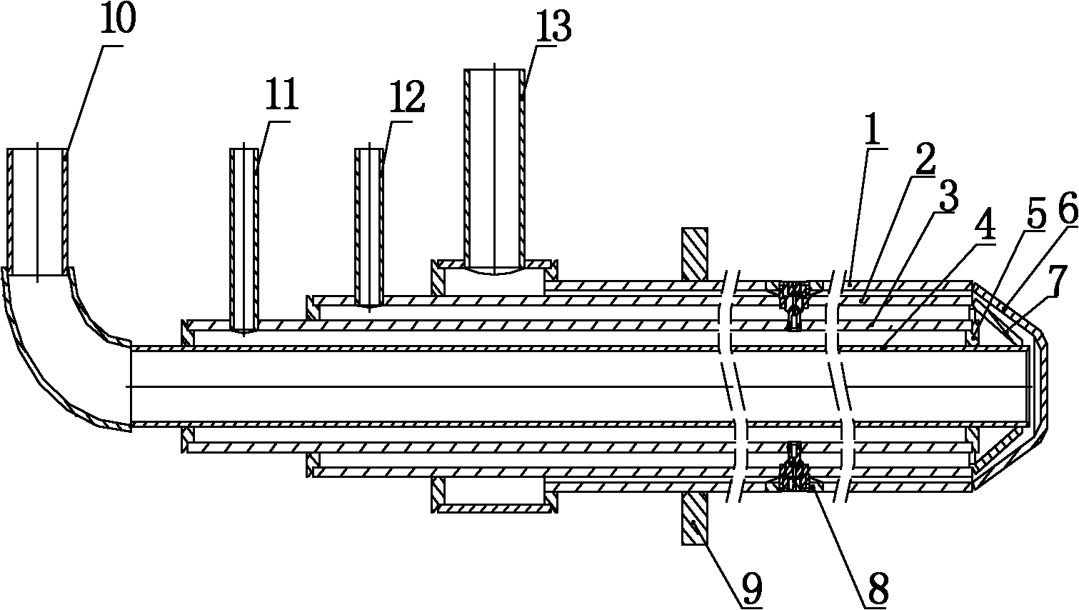
[0027] The SNCR denitrification multi-nozzle long gun injector includes a gun body assembly and at least two nozzles. The gun body assembly includes a pipeline assembly, an input assembly, and a gun head. The pipeline assembly includes a cooling water input pipe 4, a urea pipe 3, and an air pipe from the inside to the outside. 2 and cooling water output pipe 1; a urea cavity is formed between the cooling water input pipe 4 and the urea pipe 3, the cooling water input pipe is an input cooling water chamber, an air cavity is formed between the urea pipe and the air pipe, the air pipe and the cooling An output cooling water cavity is formed between the water output pipes, and the input assembly includes a water inlet connector 10 arranged at the inlet end of the cooling water inlet pipe, a urea connector 11 arranged at the inlet end of the urea pipe, an air connector 12 arranged at the inlet end of the air pipe, and a set At the water outlet joint 13 at the outlet end of the cooli...
PUM
 Abstract
Description
Claims
Application Information