
Heat direct reduced iron conveyor

A technology for conveyors and reduced iron, applied to conveyors, conveyor objects, transportation and packaging, etc., can solve secondary oxidation and other problems, achieve the effects of reducing energy consumption, shortening production cycle, and improving production efficiency

Inactive Publication Date: 2011-08-24
秦皇岛西重所燕大重型机械研究院有限公司
View PDF5 Cites 5 Cited by
  • Summary
  • Abstract
  • Description
  • Claims
  • Application Information

AI Technical Summary

Problems solved by technology

However, charging hot direct reduced iron into an electric furnace to produce molten steel is not a common technique
[0005] After completion of the reduction process, the DRI is very hot, so that it is very prone to secondary oxidation problems when the DRI is sent from the DRI plant to the steelmaking workshop

Method used


Image

  • Heat direct reduced iron conveyor
  • Heat direct reduced iron conveyor
  • Heat direct reduced iron conveyor

Examples


Embodiment 1

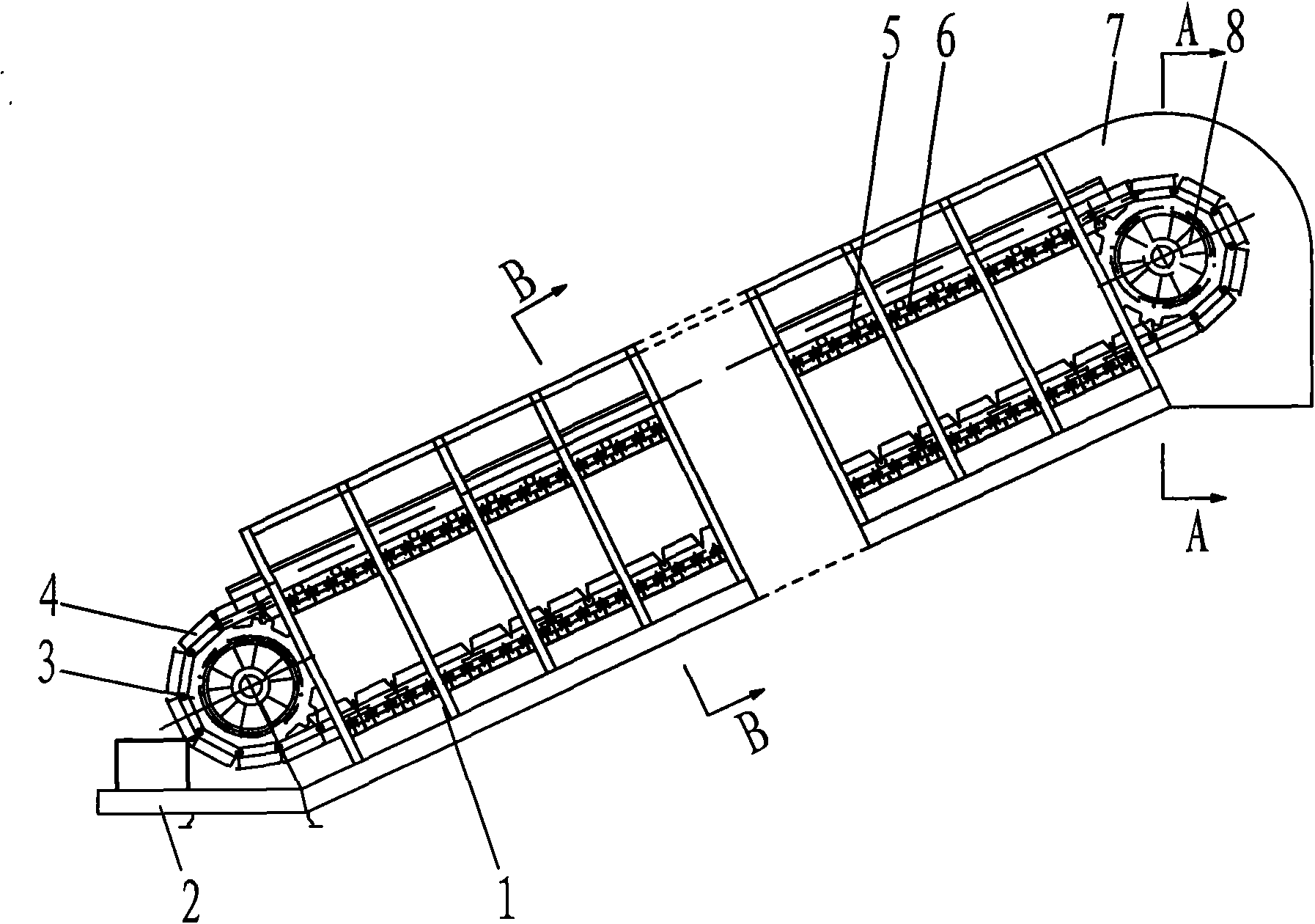
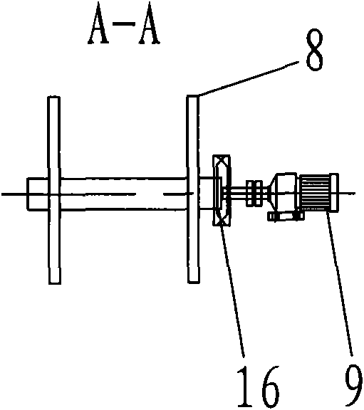
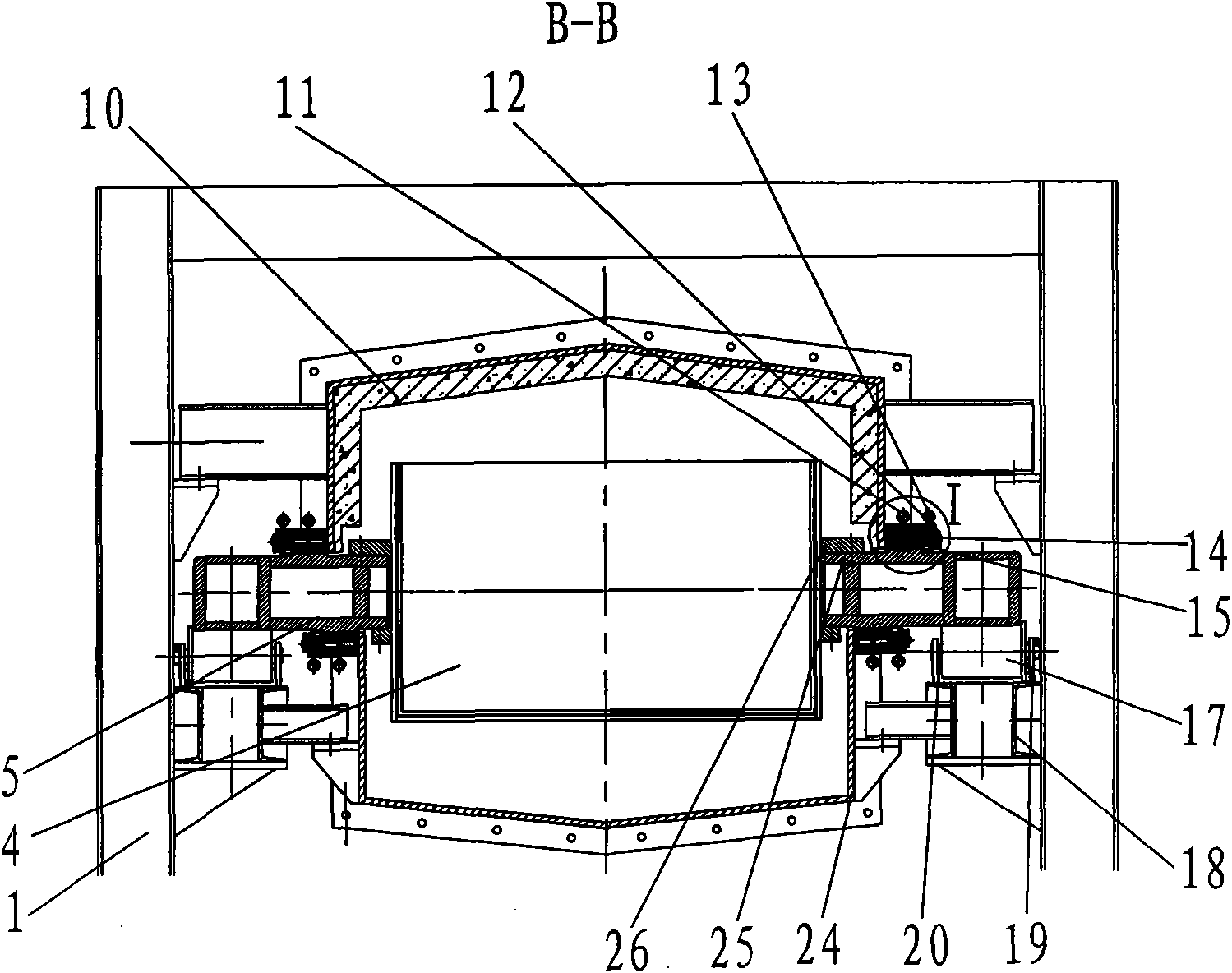
[0026] figure 1 It is an embodiment disclosed by the present invention, the frame 1 of the hot direct reduced iron conveyor is fixed on the platform 2, the unloading bin 7 is installed at the rear of the conveyor, and the driving sprocket 8 is output by the motor 9 Driven by shaft-connected reducer 16, driven sprocket 3 is installed at the front of said frame 1 and driving sprocket 8 is installed at the rear, and roller track 6 is set between driven sprocket 3 and driving sprocket 8. The tooth profiles of driving sprocket 8 and driven sprocket 3 are uniform speed tooth profiles. The two sides of the transport trolley 4 are respectively connected with the chain links 5: the chain link sealing slideway 27 is processed on the chain link upper side plate 25 of the chain link 5, the trolley side ear 26 of the transport trolley 4 is connected with the chain link of the chain link 5 The upper side plate 25 is connected by bolts; another scheme is: the box body of the material transp...

Embodiment 2

[0030] Figure 8 It is another embodiment disclosed by the present invention. The structure of the hot direct reduced iron conveyor is basically the same as that of Embodiment 1, the difference is that only the upper sealing cover is set on the upper part of the transport trolley 4 in advance of meeting the requirements of sealing and heat preservation 10, and the lower sealing cover 24 is not provided.

[0031] In Embodiment 1 and Embodiment 2, the transport trolley 4 with the chain link sealing slideway 27 processed on the upper side plate 25 of the chain link can be used, or the trolley sealing slideway 29 processed on the side ear 28 at the upper end of the trolley can be used. Material delivery trolley 4, its structure is relatively compact on the material delivery trolley 4 of trolley sealing slideway 29 on the upper end side ear 28 of the trolley.


PUM


Abstract

The invention discloses a heat direct reduced iron conveyor which is characterized in that: a driven sprocket (3) is arranged at the front of a conveyor rack (1), and a driving sprocket (8) is arranged at the back of the conveyor rack (1); a roller track (6) is arranged between the driven sprocket (3) and the driving sprocket (8), and the two sides of a material conveying carriage (4) are respectively connected with chain links (5); a chain formed by the chain links (5) runs on the roller track (6), and upper and lower heat insulation sealing covers (10,17) are fixed on the rack (1); and spring slide block slideway devices are used for sealing edges of the two sides of the upper and lower heat insulation sealing covers (10,17) and the chain links (5) at the two sides. In the heat direct reduced iron conveyor, the heat direct reduced iron is conveyed, and simultaneously, heat direct reduced iron can be insulated from heat and oxygen so as to avoid oxidation, so that the conditions are created for sending the heat direct reduced iron into an electric furnace at a high temperature; and the production cycle is shortened, the productivity is improved, and the energy loss is reduced.

Description

technical field [0001] The invention relates to the technical field of conveying bulk materials, in particular to a thermal direct reduced iron conveyor, which is mainly used for high-temperature transportation of high-temperature thermal direct reduced iron, and during the transportation process, the thermal direct reduced iron Sealed and insulated. Background technique [0002] Direct reduced iron has proven to be an alternative to conventional blast furnace hot metal, and the direct reduction process is a very efficient production process. The development of the direct reduction iron production process started 35 years ago and since then many safe and reliable direct reduction processes have been introduced into steel production. Since the end of 1990s, the production of direct reduced iron has become more and more important in the regional economy. In recent years, the growth rate of global direct reduced iron production has reached 9%, and the output has doubled every...

Claims


Application Information

Patent Timeline
Patent Type & Authority Applications(China)
IPC IPC(8): B65G17/12B65G21/08B65G49/00
Inventor 白明华张少壮葛俊礼
Owner 秦皇岛西重所燕大重型机械研究院有限公司
Learn More