Pipeline defect surface integrity detection device and detection method

A technology of surface integrity and detection device, applied in pipeline systems, mechanical equipment, gas/liquid distribution and storage, etc., can solve problems such as difficulty in accurately judging the degree of pipeline damage and different detection sensitivity

Inactive Publication Date: 2011-08-24
HARBIN INST OF TECH
View PDF4 Cites 21 Cited by
  • Summary
  • Abstract
  • Description
  • Claims
  • Application Information

AI Technical Summary

Problems solved by technology

[0004] In order to solve the problem that the existing in-pipe detection devices have different detection sensitivities to different materials and different types of defects, the measurement d...

Method used


Image

  • Pipeline defect surface integrity detection device and detection method
  • Pipeline defect surface integrity detection device and detection method

Examples


specific Embodiment approach 1

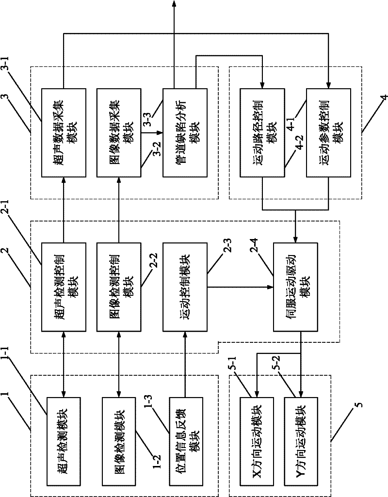
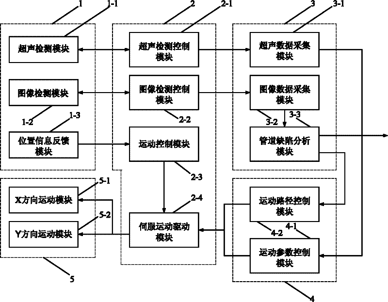
[0015] Specific implementation mode one: combine figure 1 Describe this embodiment, this embodiment is made up of detection component 1, control component 2, data acquisition component 3, motion control component 4 and motion execution component 5; The detection data signal input and output terminals are connected, and the image detection data signal output and input terminals of the detection component 1 are connected with the image detection data signal input and output terminals of the control component 2; the position information data output terminals of the detection component 1 are connected with the position information data of the control component 2 The input end is connected, and the ultrasonic acquisition data output end of control assembly 2 is connected with the ultrasonic acquisition data data input end of data acquisition assembly 3, and the image acquisition data output end of control assembly 2 is connected with the image acquisition data input end of data acqu...

specific Embodiment approach 2

[0016] Specific implementation mode two: combination figure 1 Describe this embodiment, the first difference between this embodiment and the specific embodiment is that the detection component 1 is composed of an ultrasonic detection module 1-1, an image detection module 1-2, and a position information feedback module 1-3; the ultrasonic detection module The output and input end of the ultrasonic detection data signal of 1-1 is the output and input end of the ultrasonic detection data signal of the detection component 1; the output and input end of the image detection data signal of the image detection module 1-2 is the image detection data of the detection component 1 Signal output and input terminals; the position information data output terminal of the position information feedback module 1-3 is the position information data output terminal of the detection component 1 . Other compositions and connection methods are the same as those in Embodiment 1.

specific Embodiment approach 3

[0017] Specific implementation mode three: combination figure 1 Describe this embodiment, the difference between this embodiment and specific embodiment 1 or 2 is that the control assembly 2 is driven by the ultrasonic detection control module 2-1, the image detection control module 2-2, the motion control module 2-3 and the servo motion The module 2-4 is composed; the ultrasonic detection data signal input and output end of the ultrasonic detection control module 2-1 is the ultrasonic detection data signal input and output end of the control assembly 2; the image detection data of the image detection control module 2-2 The signal input and output end is the image detection data signal input and output end of the control assembly 2; the position information data input end of the motion control module 2-3 is the position information data input end of the control assembly 2; the motion control module 2 The servo drive control signal output end of -3 is connected with the servo d...


PUM


Abstract

The invention discloses a pipeline defect surface integrity detection device and a pipeline defect surface integrity detection method for solving the problem that the damage degree of a pipeline is difficult to judge because the conventional pipe detection device has different detection sensitivities for different materials and defects of different types and the measurement data are independent with one another. The ultrasonic detection data signal output/input end, the image detection data signal output/input end and the position information data output end of a detection assembly are connected with the ultrasonic detection data signal input/output end, the image detection data signal input/output end and the position information data input end of a control assembly respectively. The method comprises the following steps of: 1, acquiring image data of a pipeline damaged surface, and calculating a pipeline defect surface area and a damage characteristic parameter; 2, detecting the thickness information in a limited area; 3, performing integrity three-dimensional entity modeling of the defect surface and the damaged area; and 4, obtaining a result by using a finite element analysis method. The device and the device can accurately judge the damage degree of the pipeline and are applied to the occasions of defect surface integrity detection.

Description

technical field [0001] The invention relates to a pipeline defect surface detection device and a detection method thereof. Background technique [0002] Buried pipelines in service are subjected to the joint action of internal and external media for a long time during use, such as water corrosion, water hammer, soil physical, chemical, electrochemical corrosion, potential defects of pipes, fatigue damage, natural or human factors, etc. , there will be mechanical cracks and corrosion points (pit or hole) on the pipe wall, which will destroy the surface integrity of the pipe body, and gradually "weaken" the pipe function and enter the accident-prone period. Therefore, combined with the defect types and characteristics of in-service pipeline damage, the detection and evaluation of defect surface integrity is the key to realize the safe operation and management of pipelines. [0003] The in-pipeline detection technology is an effective means to detect the integrity of the defec...

Claims


Application Information

Patent Timeline
IPC IPC(8): F17D5/06
Inventor 白桦高立新陈冰
Owner HARBIN INST OF TECH
Why Eureka
Try Eureka