Lighting device and lighting system
A technology for lighting equipment and appliances, which is applied in lighting devices, fixed lighting devices, lighting and heating equipment, etc., can solve problems such as wasting electricity, and achieve the effect of promoting energy saving and improving brightness.
- Summary
- Abstract
- Description
- Claims
- Application Information
AI Technical Summary
Problems solved by technology
Method used
Image
Examples
Embodiment approach 1
[0026] Embodiment 1 of the lighting fixture of the present invention will be described in detail with reference to the drawings.
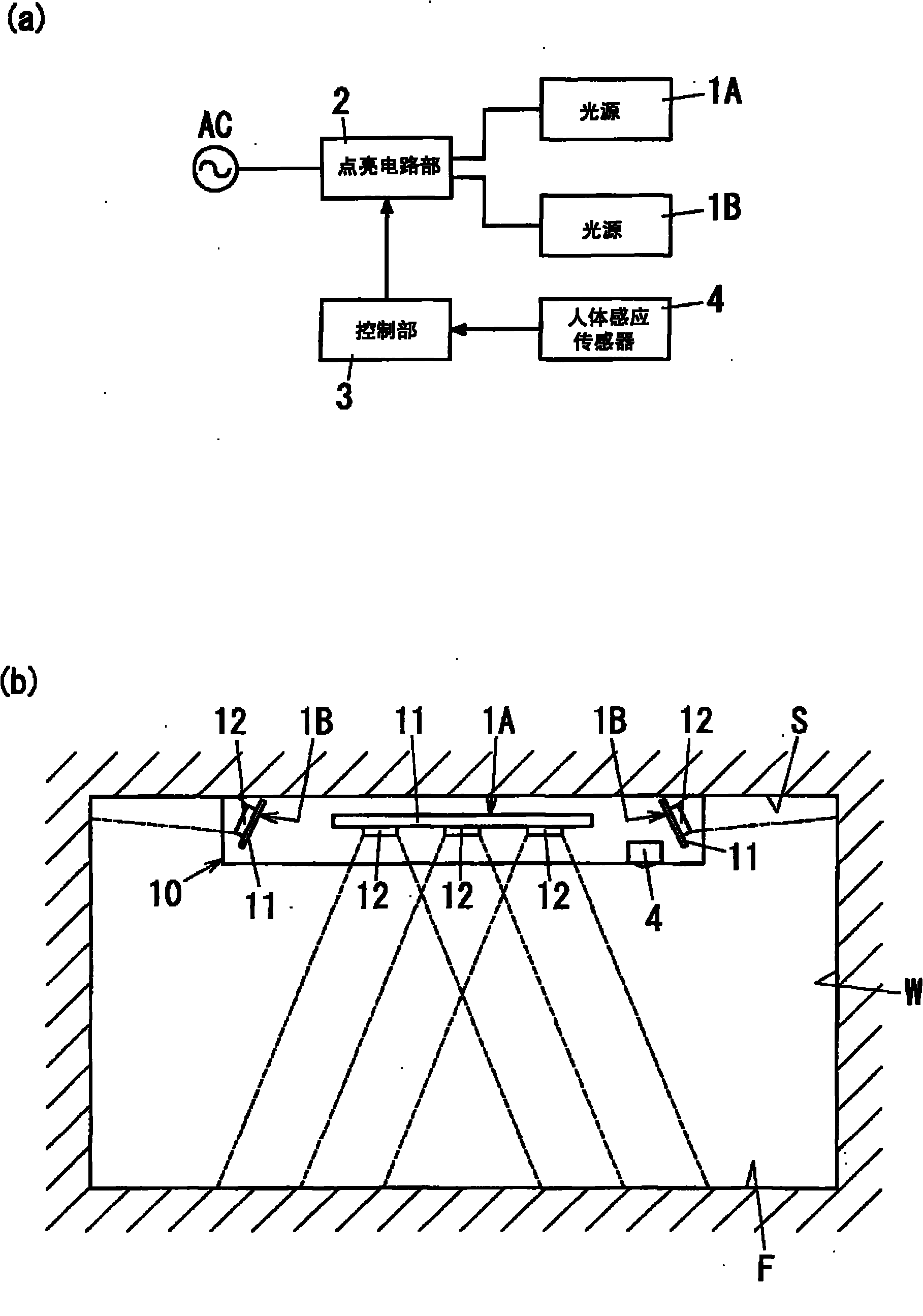
[0027] like figure 1 As shown in (a), the lighting fixture of this embodiment includes: two kinds of light sources 1A, 1B; a lighting circuit part 2 for independently turning on and off (or dimming) each light source 1A, 1B; A control unit 3 for controlling; a human body induction sensor 4 . The lighting fixture also has a fixture main body 10, and the fixture main body 10 is as figure 1 As shown in (b), the light sources 1A, 1B, the lighting circuit unit 2, the control unit 3, and the human body sensor 4 are held, and installed on the ceiling S of the lighting space.
[0028] The light sources 1A and 1B are configured by mounting a light-emitting diode 12 for emitting white light on a heat-dissipating mounting substrate 11 . One type of light source 1A is arranged at the center of the device main body 10 and radiates light toward the floor F of...
Embodiment approach 2
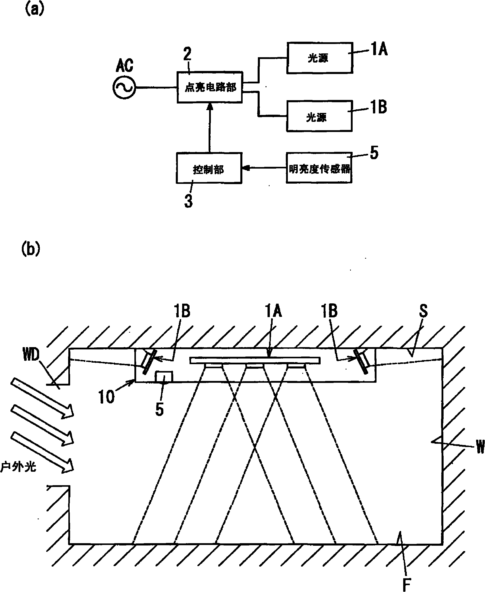
[0036] like figure 2 As shown, the lighting fixture of this embodiment is characterized by having a brightness sensor 5 instead of the human body sensor 4 . Among them, the configuration is the same as that of the first embodiment except that a brightness sensor 5 is provided instead of the human body sensor 4 . Therefore, the same reference numerals are assigned to the same constituent elements as those in the first embodiment, and description thereof will be omitted.
[0037] The brightness sensor 5 has a photosensitive element such as a photodiode, a comparator (Comparator) for comparing the output of the photosensitive element with a threshold value, etc., and when the surrounding brightness (illuminance) exceeds a predetermined value, a high-level signal (outdoor Light detection signal) is output to the control unit 3.
[0038] Here, if figure 2 As shown in (b), a window WD is opened on the wall surface of the lighting space, and outdoor light (sunlight) enters throu...
Embodiment approach 3
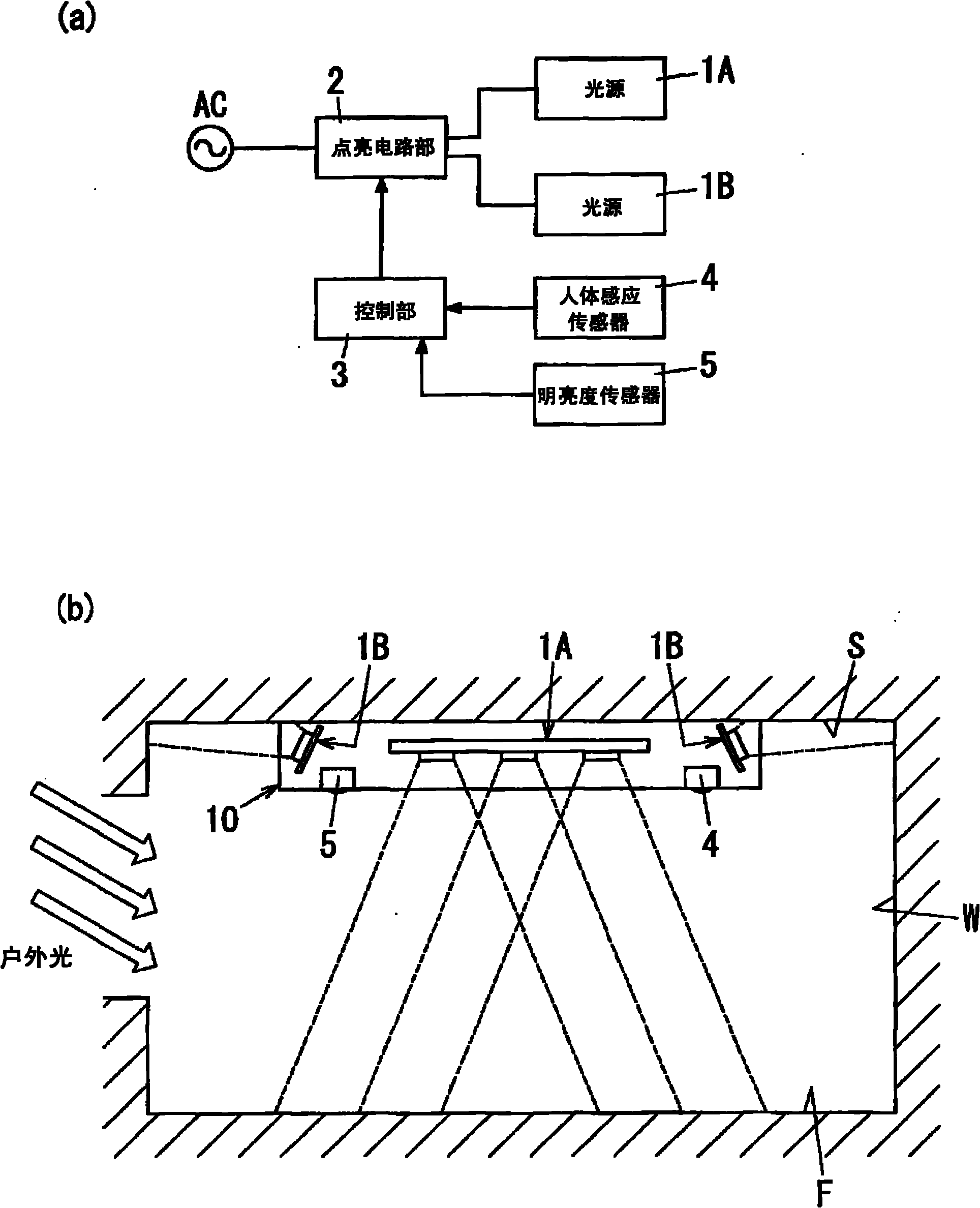
[0043] like image 3 As shown, the lighting fixture of this embodiment is characterized by including a human body sensor 4 and a brightness sensor 5 . Here, the basic structure of this embodiment is the same as that of Embodiment 1 and Embodiment 2, and therefore, the same reference numerals are assigned to the same constituent elements, and description thereof will be omitted.
[0044] The control operation of the control unit 3 in this embodiment will be described. When the control unit 3 outputs the human body detection signal from the human body induction sensor 4, or when the outdoor light detection signal is output from the brightness sensor 5, the switch of the lighting circuit unit 2 is turned on, so that both of the two light sources 1A and 1B are turned on. . Therefore, the light irradiated from one light source 1A to the floor F can provide sufficient illuminance required for the work surface, and the light irradiated from the other light source 1B to the ceiling ...
PUM
 Abstract
Description
Claims
Application Information
 - R&D
- Intellectual Property
- Life Sciences
- Materials
- Tech Scout
- Unparalleled Data Quality
- Higher Quality Content
- 60% Fewer Hallucinations
Browse by: Latest US Patents, China's latest patents, Technical Efficacy Thesaurus, Application Domain, Technology Topic, Popular Technical Reports.
© 2025 PatSnap. All rights reserved.Legal|Privacy policy|Modern Slavery Act Transparency Statement|Sitemap|About US| Contact US: help@patsnap.com


