
Imaging method of seismic wave fields between inclined wells

A technology of seismic wave field and imaging method, which is applied in the fields of seismology and seismic signal processing for well logging records, and can solve the problems of poor fidelity and amplitude preservation of imaging results, prominent anisotropy problems, and unclean wave field separation, etc. problems, to achieve the effects of fast calculation speed, improved imaging accuracy, and good kinematics and dynamics characteristics

Inactive Publication Date: 2011-08-24
CHINA NAT OFFSHORE OIL CORP +2
View PDF0 Cites 17 Cited by
  • Summary
  • Abstract
  • Description
  • Claims
  • Application Information

AI Technical Summary

Problems solved by technology

Most existing conventional crosswell seismic stacking imaging methods based on ray theory have poor fidelity and amplitude preservation of imaging results
Conventional reflected wave stacking imaging methods, such as VSP-CDP stacking imaging, require the input to be a single wave field, which often results in unsatisfactory imaging results due to unclean wave field separation
For oil layers that have been developed for many years, the inter-well reservoir changes relatively large, and the anisotropy problem is more prominent, and the conventional wave field imaging method always has certain problems

Method used


Image

  • Imaging method of seismic wave fields between inclined wells
  • Imaging method of seismic wave fields between inclined wells
  • Imaging method of seismic wave fields between inclined wells

Examples


Embodiment Construction

[0016] The present invention will be described in detail below in conjunction with the accompanying drawings and embodiments.

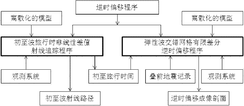
[0017] Such as figure 1 As shown, the method of the present invention includes two parts: first arrival ray tracing and reverse time migration imaging. First-arrival ray tracing mainly calculates the first-arrival time from the shot point (source S) to each grid node through the input discretized model and observation system, which is used as the imaging condition for reverse time migration imaging; reverse time migration imaging mainly Through the input discretized model and observation system and the pre-stack full wave field or single wave field record, and using the first arrival time as the imaging condition of reverse time migration imaging, the wave field is extrapolated and imaged in the reverse time direction to achieve Purpose of reverse time migration imaging.

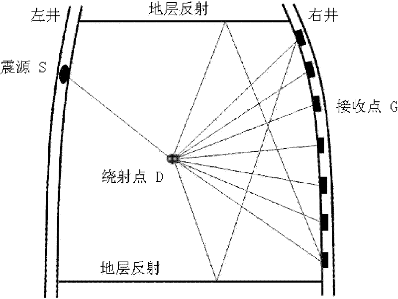
[0018] Such as figure 2 As shown, for two adjacent inclined wells, the left...


PUM


Abstract

The invention relates to an imaging method of seismic wave fields between inclined wells, comprising the following steps of: 1) scattering and gridding space areas between two adjacent inclined wells; taking each of the grid nodes as a secondary source point; 2) calculating the time TSD needed for transmitting a seismic focus S to each of the grid nodes according to a first-motion wave travel-time nonlinear interpolation ray-tracking method; 3) taking the actually recorded wave field as source by a receiving point; extrapolating the reverse time of each of the grid nodes to the TSD moment by using a speed-stress-first order differential equitation staggered gridding finite difference method, wherein the wave field at the moment is the image of the grid point; and 4) when the wave field is transmitted to a medium border, as the border wave impedance difference is large, using a completely matched layer to absorb the border, namely a PML layer; absorbing and attenuating the wave field so that the wave field cannot return to the medium and form interference.

Description

technical field [0001] The invention relates to the field of energy exploration and development, in particular to an imaging method for an interwell seismic wave field of an offshore inclined well. Background technique [0002] At present, the cross-well seismic imaging method has developed from the ray theory to the elastic wave theory, and from the vertical well to the deviated well imaging method. The crosswell seismic wave field is complex and rich, including both upgoing and downgoing reflection wave fields, and it is difficult to separate the wave fields. Especially in the case of offshore inclined wells, the difficulty of separation is even more obvious. Most existing conventional crosswell seismic stacking imaging methods based on ray theory have poor fidelity and amplitude preservation of imaging results. Conventional reflection wave stacking imaging methods, such as VSP-CDP stacking imaging, require the input to be a single wave field, which often leads to unsati...

Claims


Application Information

Patent Timeline
IPC IPC(8): G01V1/42G01V1/28
Inventor 李绪宣孙渊胡光义金其虎范廷恩马德堂高云峰李辉峰张良李敬功董建华王玉贵
Owner CHINA NAT OFFSHORE OIL CORP
Learn More