Special-shaped wire sheath for optical fiber unit in special optical cable

An optical fiber unit and optical cable technology, applied in the field of special-shaped wire sheath, can solve the problems of deformation of the protective tube of the optical fiber unit, increased optical fiber transmission loss, large diameter of the optical cable cross-section, etc. Powerful, compact effect

Inactive Publication Date: 2011-08-24
章君旭 +1
View PDF3 Cites 1 Cited by
  • Summary
  • Abstract
  • Description
  • Claims
  • Application Information

AI Technical Summary

Problems solved by technology

Both of these situations will cause the optical fiber unit protection tube to deform and compress the optical fiber, which will increase the transmission loss of the optical fiber in a slight case, and will cause the optical fiber to break in a severe case.
At the same time, the circumferentially arranged sheath formed by the round single wires has many gaps and a large diameter, resulting in a large cross-sectional diameter of the entire optical cable, and the horizontal contact between the round single wires is line contact, and the compressive performance is poor.
[0004] The second technology: the split circular tube sheath composed of fan-shaped metal wires, when a fan-shaped wire is directly subjected to lateral pressure, it will be immediately transmitted to the adjacent fan-shaped wires, and the decomposition of the lateral pressure improves the direct lateral pressure resistance of the optical fiber unit. ability, but when bent, the edge of the fan-shaped line will have a position slip, which will still cause the fiber unit protection tube to deform and compress the fiber

Method used


Image

  • Special-shaped wire sheath for optical fiber unit in special optical cable
  • Special-shaped wire sheath for optical fiber unit in special optical cable
  • Special-shaped wire sheath for optical fiber unit in special optical cable

Examples


Embodiment Construction

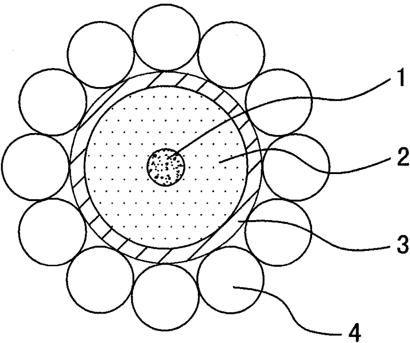
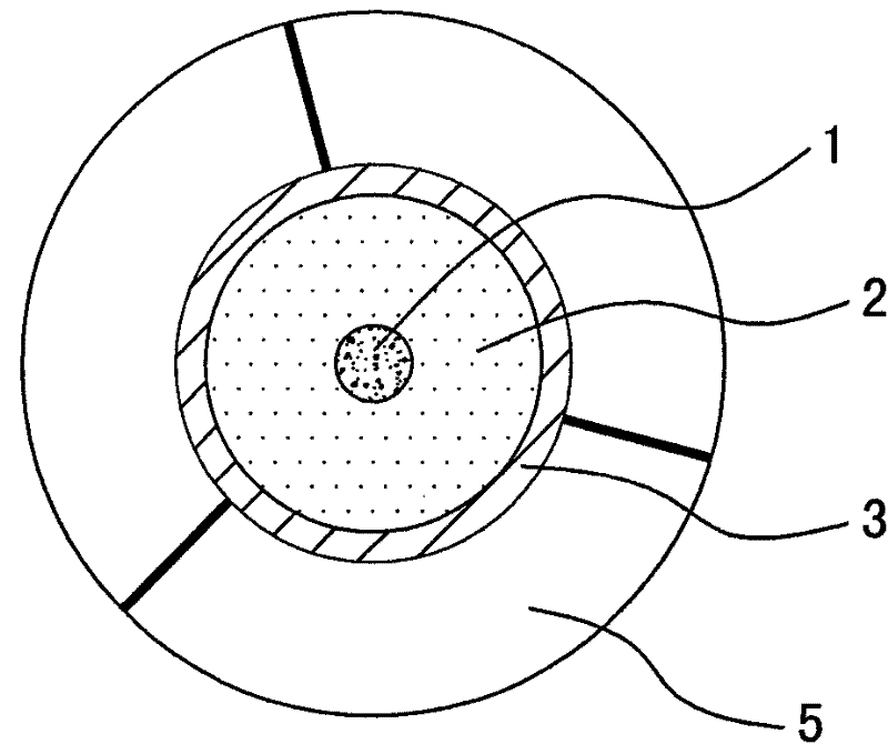
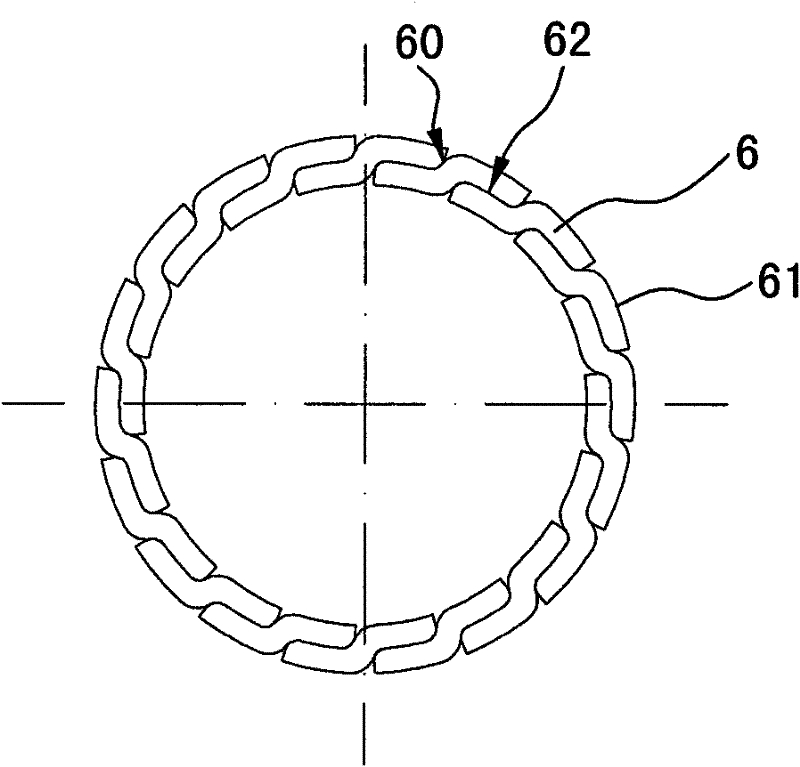
[0015] The invention relates to a special-shaped wire sheath of an optical fiber unit in a special optical cable, such as Figure 3-Figure 6 As shown, it includes special-shaped wires made of metal materials, and the special-shaped wires are arranged into a circular sheath, and the optical fiber unit is protected in the circular sheath. The optical fiber unit is as follows figure 1 , figure 2 As shown, it consists of an optical fiber 1, a water-blocking ointment 2 and a protective tube 3, and is characterized in that the special-shaped wire is a metal sheet 6, and there is an overlapping part between the former metal sheet and the latter metal sheet through mutual The cross section is overlapped to form a circular tube, and it is twisted in a helical shape. Each metal sheet material 6 of this scheme has partial overlapping overlapping arrangement, and the gap between each other is small, and the lateral pressure resistance strength is high, and at the same time compared with...


PUM


Abstract

The invention relates to a special-shaped wire sheath for an optical fiber unit in a special optical cable. The special-shaped wire sheath comprises special-shaped wires made of a metal material and a circular sheath formed by arranging the special-shaped wires. The special-shaped wire sheath is characterized in that: the special-shaped wires are metal sheets; and overlapped parts between front metal sheets and rear metal sheets are in lap joint mutually to form a horizontal tubular section and are spirally twisted. Certain parts of all the metal sheets are arranged in an overlapped way, the gaps between the sheets are small, and the lateral pressure resistance is high. Compared with a twisting layer sheath which is formed by arranging circular steel wires (metal single wires), the special-shaped wire sheath has small gaps, a compact structure and a small diameter under the condition of the same effective cross-sectional areas, so that the whole forming optical cable has small diameter and light weight, and the cost of production, transportation, construction and maintenance is saved. Particularly, the special-shaped wires are the sheets, certain parts of the sheets are arranged in a mutually overlapped way, and the sheets have thin walls, so that the special-shaped wire sheath has high pressure and tensile deformation resistance and low impacts of lateral pressure on the optical fiber when the optical fiber unit is bent.

Description

technical field [0001] The invention relates to optical cables, in particular to special-shaped wire sheaths for optical fiber units in special optical cables. Background technique [0002] The optical fiber unit is the core component of the optical cable, and it is also the most delicate part of the optical cable. The optical fiber unit is composed of optical fiber 1, water-blocking ointment 2 and protection tube 3, and the protection tube has two types: metal or non-metal. Non-metallic protective tubes are generally some kind of plastic tubes, usually used for conventional optical cables, relying on the cable sheath to provide protection for the optical fiber unit; metal protective tubes are generally stainless steel, copper or aluminum tubes, usually used for submarine optical cables, power optical cables and other special Due to the influence of harsh environments such as water pressure, wind pressure, and ice coating, the optical fiber cable should provide additional p...

Claims


Application Information

Patent Timeline
Patent Type & Authority Applications(China)
IPC IPC(8): G02B6/44
Inventor 章君旭单才华
Owner 章君旭
Why Eureka
Try Eureka