Borehole ground potential measuring electrode

A technology for measuring electrodes and ground potential, which is applied in measurement, wellbore/well parts, earthwork drilling and production, etc. It can solve problems such as management confusion, short steel cages, and piling depths that do not meet the requirements, so as to increase the signal-to-noise ratio, Effect of suppressing interference and improving measurement accuracy

Inactive Publication Date: 2013-04-24
JIANGSU FANGJIAN ENG QUALIFICATION TESTING
View PDF5 Cites 0 Cited by
  • Summary
  • Abstract
  • Description
  • Claims
  • Application Information

AI Technical Summary

Problems solved by technology

During the construction of concrete piles, the following problems often occur: 1) The placement of the reinforcement cage is not correct, and it is skewed and stuck in a certain part of the well wall, resulting in the failure of the reinforcement cage to go down to the specified depth; 2) The rock and soil conditions are more complicated. In the rock-socketed pile area, the depth of the pile piles in each location is different, and the length of the corresponding piles is different. During construction, the corresponding pile piles should be lowered into the corresponding wells. However, due to the chaotic management during construction, the steel cage 3) A small number of builders, in order to make illegal profits, are short and short when manufacturing steel cages, and the length of the steel cages does not meet the design requirements, resulting in the depth of piles. Did not meet the requirements
[0004] The existing electrode is generally a metal electric rod. Due to the electrochemical process, an electrode polarization electric field is generated on its surface, which has a non-negligible impact on the weak potential gradient measurement, and even seriously hinders the accuracy of the ground potential. Measurement

Method used


Image

  • Borehole ground potential measuring electrode
  • Borehole ground potential measuring electrode
  • Borehole ground potential measuring electrode

Examples


Embodiment Construction

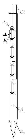
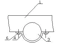
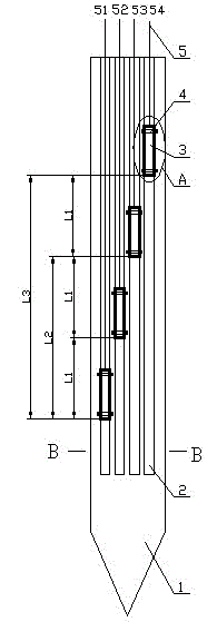
[0020] control figure 1 , The ground potential measuring electrode of the present invention is mainly composed of an insulating rod 1, an electrode bottle 3 with a copper sulfate solution built in it, and a wire 5. The insulating rod 1 of the present embodiment is made of Bakelite (also can be made of insulating plastic), and the cross section of the insulating rod 1 along the width direction is rectangular, see figure 2 , the front end of which is a tip that facilitates sinking. Four semicircular grooves 2 are arranged on one side of the insulating rod 1, and the four semicircular grooves 2 are arranged parallel and side by side along the width direction of the insulating rod. The radius of the semicircular channel is equivalent to the radius of the electrode bottle 3, and an electrode bottle 3 is placed in the channel according to the length direction and the direction of the channel in each channel. The electrode bottles 3 placed in the four semicircular channels 2 are a...


PUM


Abstract

The invention relates to a borehole ground potential measuring electrode. The borehole ground potential measuring electrode comprises an insulation rod, a plurality of electrode bottles containing copper sulphate solution and a plurality of wires, wherein one end of each wire is arranged in the corresponding electrode bottle and contacts the copper sulphate solution in the electrode bottle, and the other end of the wire is extended out of the electrode bottle; a copper sulphate solution effusion point is arranged on each electrode bottle; the electrodes bottles are fixed on the insulation rodat identical intervals in a manner that the length directions of the electrode bottles are coincident to the length direction of the insulation rod. In the invention, the copper sulphate solution is used for displacing a metal rod to contact borehole media, so that the problem that the electrodes of the metal rod are polarized is avoided; and a plurality of sealing bottles which contain the copper sulphate solution and are arranged at identical intervals are used as the electrodes and the electrode distance is adjustable, so that different electrode distances can be selected according to the interference degree of industrial stray current of a measuring place, thereby inhibiting interference, increasing the signal to noise ratio, and improving the measurement precision and the quality of measured data.

Description

technical field [0001] The invention relates to a technique for measuring potential gradients in well drilling, in particular to an electrode for measuring ground potential in wells. Background technique [0002] In the underground drilling required for geological prospecting, oil exploration, etc., it is usually necessary to obtain some relevant data through potential measurement in the well. In recent years, this kind of potential measurement technology has been used in engineering survey and quality inspection of construction projects. For example, the measurement of the depth of the steel cage sinking into the well in the construction of concrete pile piles. During the construction of concrete piles, the following problems often occur: 1) The placement of the reinforcement cage is not correct, and it is skewed and stuck in a certain part of the well wall, resulting in the failure of the reinforcement cage to go down to the specified depth; 2) The rock and soil condition...

Claims


Application Information

Patent Timeline
Patent Type & Authority Patents(China)
IPC IPC(8): E21B47/00
Inventor 吴丽雅潘伟洪延源张桂叶金元唐秋琴
Owner JIANGSU FANGJIAN ENG QUALIFICATION TESTING
Why Eureka
Try Eureka