Hydraulic direct-drive vertical multi-cylinder mud pump

A mud pump and hydraulic cylinder technology, applied in the field of mud pumps, can solve the problems of complex reversing control mechanism, short service life of wearing parts, increased volume and weight, etc. compact effect

Active Publication Date: 2012-09-05
XIAN RES INST OF CHINA COAL TECH& ENG GROUP CORP
View PDF2 Cites 0 Cited by
  • Summary
  • Abstract
  • Description
  • Claims
  • Application Information

AI Technical Summary

Problems solved by technology

[0005] 2. Increasing the number of piston cylinders can increase displacement and reduce flow unevenness, but the structure is complicated, the volume and weight increase, and processing is difficult;
[0006] 3. Increasing the stroke times of the piston will result in serious wear and short service life of wearing parts;
[0007] The disadvantage of the hydraulically driven reciprocating mud pump is that the hydraulic motor is used as a rotary input mud pump. In addition to the shortcomings of the three-cylinder crank mud pump, it also has low efficiency due to multiple conversions of energy.
[0008] A hydraulic cylinder drives a reciprocating mud pump, such as patent CN200810031890.7, which proposes a hydraulic mud pump composed of two or more combined cylinders, and uses the hydraulic oil discharged from the cylinder in the return stroke to drive the cylinder in the feed stroke The movement of the machine adopts mechanical contact control switch to achieve reversing, and reduces the pulsation of discharge flow by increasing the number of combined oil cylinders, but its reversing structure is complex and its reliability is poor
Patent CN02257780.7 uses a parallel double-cylinder single-acting hydraulic mud pump to control the cylinder piston to reversing with a magnetic damping commutator with a difference of 180°, and uses an accumulator (air bag) to fill the instantaneous time when the two cylinders work alternately. Pressure fluctuations, complex reversing control mechanism, and poor reliability

Method used


Image

  • Hydraulic direct-drive vertical multi-cylinder mud pump
  • Hydraulic direct-drive vertical multi-cylinder mud pump
  • Hydraulic direct-drive vertical multi-cylinder mud pump

Examples


Embodiment Construction

[0040] The present invention will be described in detail below in conjunction with the accompanying drawings and specific embodiments.

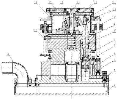
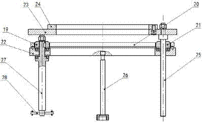
[0041] see figure 1 , 2, 9, the present invention comprises a water suction box 1, a drainage box 3, an oil inlet valve body 17, a hydraulic cylinder box 6, a lifting device 9, and the oil inlet valve body 17, the hydraulic cylinder box 6, and the drainage box 3 are stacked The formula structure is arranged on the upper part of the water suction box 1 in turn, and any two are connected by bolts and studs arranged in the circumferential direction. The upper part of the oil inlet valve body 17 is provided with a wobble box 16; A wobble plate 14 is set, the inclined shaft 12 is fixed in the middle of the wobble plate 14 through a pair of bearings, the pump shaft 13 set at the center of the wobble plate box 16 is connected with the inclined shaft 12 through a flat key, and the pump shaft 13 set at the center of the oil inlet valve body 17 The o...


PUM


Abstract

The invention relates to a hydraulic direct-drive vertical multi-cylinder mud pump. At present, most of domestic and foreign mud pumps adopt a mechanical driving manner, such as a crank connecting rod, a cam, a swash plate and the like to convert the rotational movement of a motor into the reciprocating linear movement of a piston so as to finish the inflow and drainage processes of the mud pumps; and some hydraulic drive reciprocating mud pumps mostly take a hydraulic motor as a rotary input, and the driving manner is similar to that of the mechanical pump. The hydraulic direct-drive vertical multi-cylinder mud pump comprises a suction box body, a drainage box body, an oil inlet valve body, a hydraulic cylinder box body and a lifting device; and the oil inlet valve body, the hydraulic cylinder box body, and the drainage box body are arranged on the upper part of the suction box body in sequence in a laminated structure, and any two of the oil inlet valve body, the hydraulic cylinder box body, and the drainage box body are connected via a bolt and a double-end stud arranged in a circumferential direction. The invention adopts the structure of driving an oil pressure cylinder piston and a water pressure cylinder piston directly by hydraulic pressure, so the hydraulic energy is converted into water energy directly, the energy loss is reduced, and the utilization efficiency is improved.

Description

technical field [0001] The invention relates to a mud pump, in particular to a hydraulic direct drive, vertical and multi-cylinder mud pump. technical background [0002] At present, most of the mud pumps at home and abroad use mechanical drive methods such as crank connecting rods, cams or swash plates to convert the rotational motion of the motor into the reciprocating linear motion of the piston to complete the inlet and outlet processes of the mud pump. In recent years, there are also some hydraulically driven reciprocating mud pumps, most of which use hydraulic motors as the rotary input, and their driving mode is similar to that of mechanical pumps; there are also hydraulic cylinders to drive reciprocating mud pumps, but their reversing control mechanism is complicated. Most of the commonly used reciprocating mud pumps are three-cylinder, single-acting crank pumps, which can meet the displacement requirements of engineering mud pumps in principle. [0003] The disadva...

Claims


Application Information

Patent Timeline
Patent Type & Authority Patents(China)
IPC IPC(8): F04B9/109F04B15/02
Inventor 殷新胜胡少韵董书宁田宏亮曹明胡亚
Owner XIAN RES INST OF CHINA COAL TECH& ENG GROUP CORP
Why Eureka
Try Eureka