Transmission speed change device

A variable speed device and constant speed technology, applied in the direction of transmission device, friction transmission device, belt/chain/gear, etc., can solve the problems of difficult design and processing of constant speed cam mechanism, long transmission route, large instantaneous impact, etc., and achieve high efficiency and reversibility, load uniformity, and smooth rotational force

Inactive Publication Date: 2011-08-31
乔海祥
View PDF4 Cites 7 Cited by
  • Summary
  • Abstract
  • Description
  • Claims
  • Application Information

AI Technical Summary

Problems solved by technology

The connecting rod mechanism is widely used because of its simple structure and easy processing, but its transmission route is long, and it is easy to generate large error accumulation; Not suitable for high-speed movement due to large dynamic load
[0003] Although the dynamic load of t

Method used


Image

  • Transmission speed change device
  • Transmission speed change device
  • Transmission speed change device

Examples


Embodiment Construction

[0021] The specific implementation of the transmission and speed change device will be described in detail below in conjunction with the accompanying drawings.

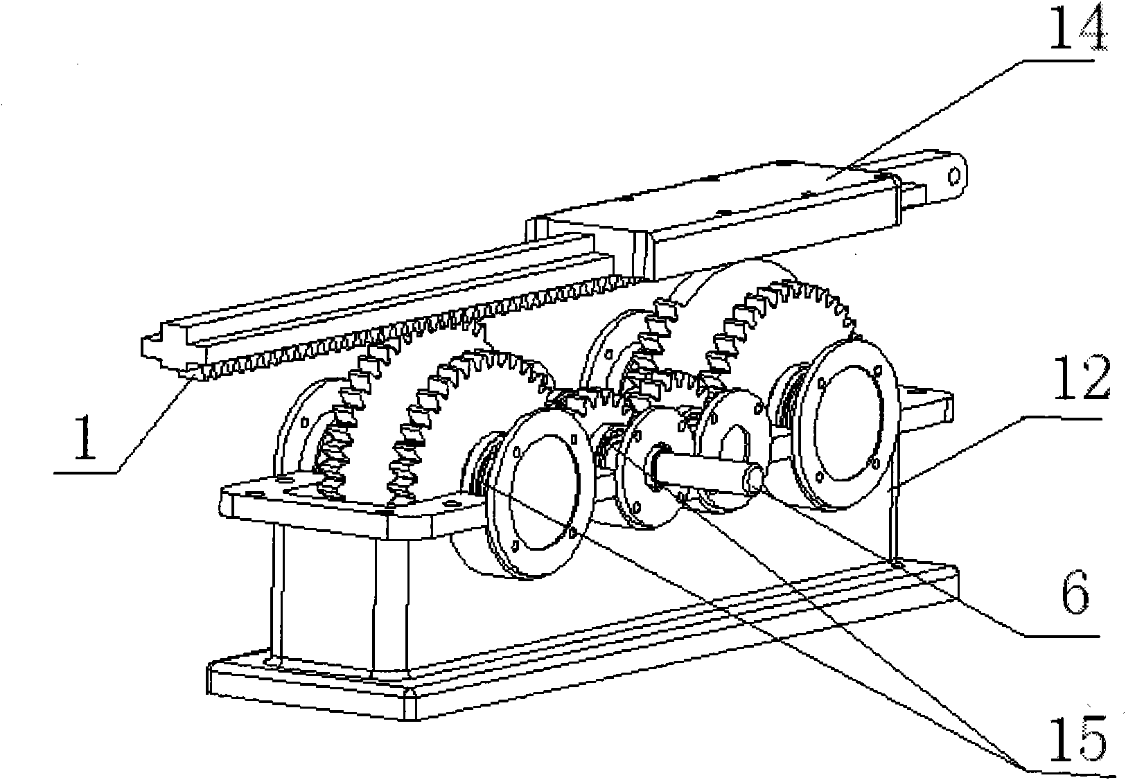
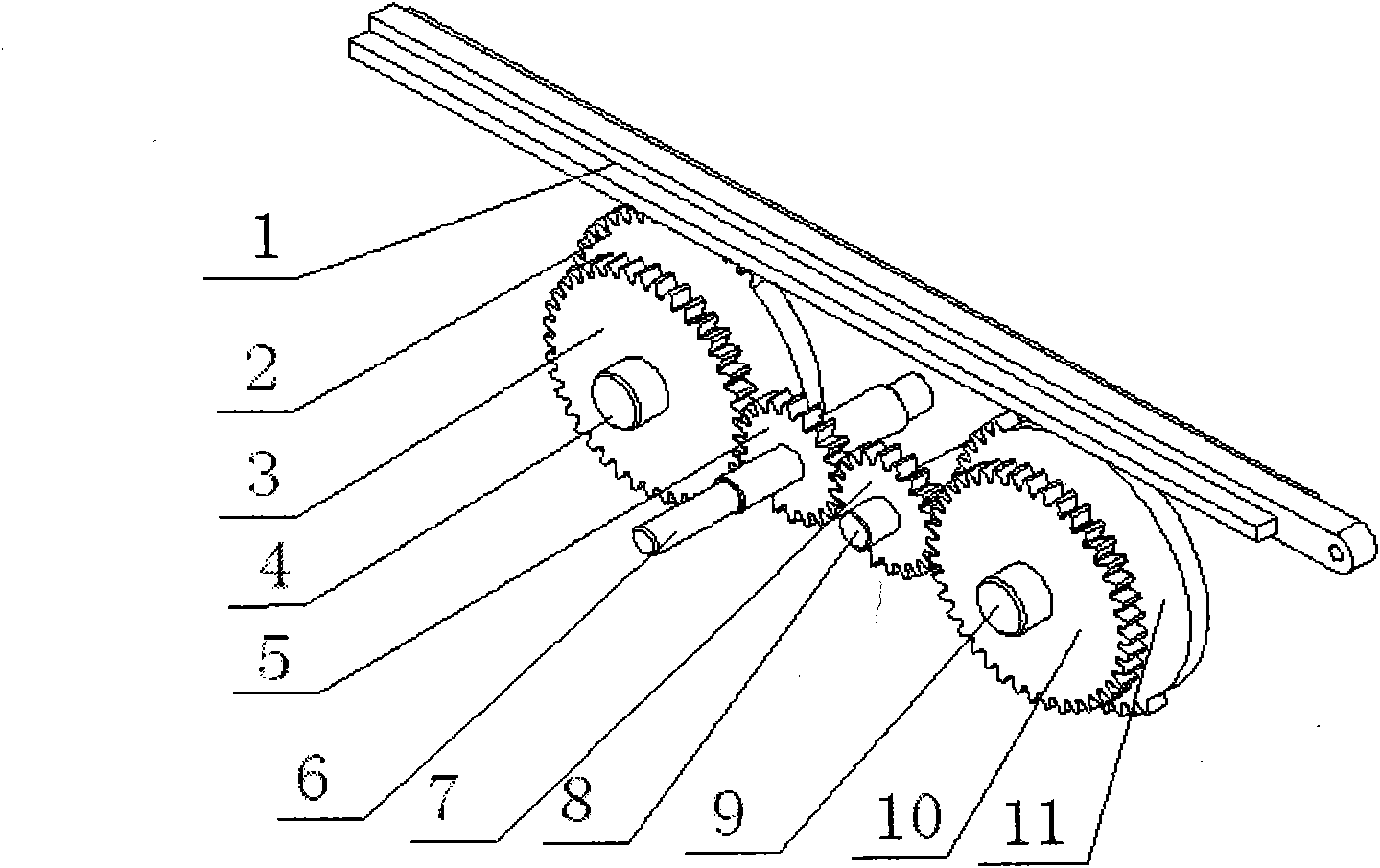
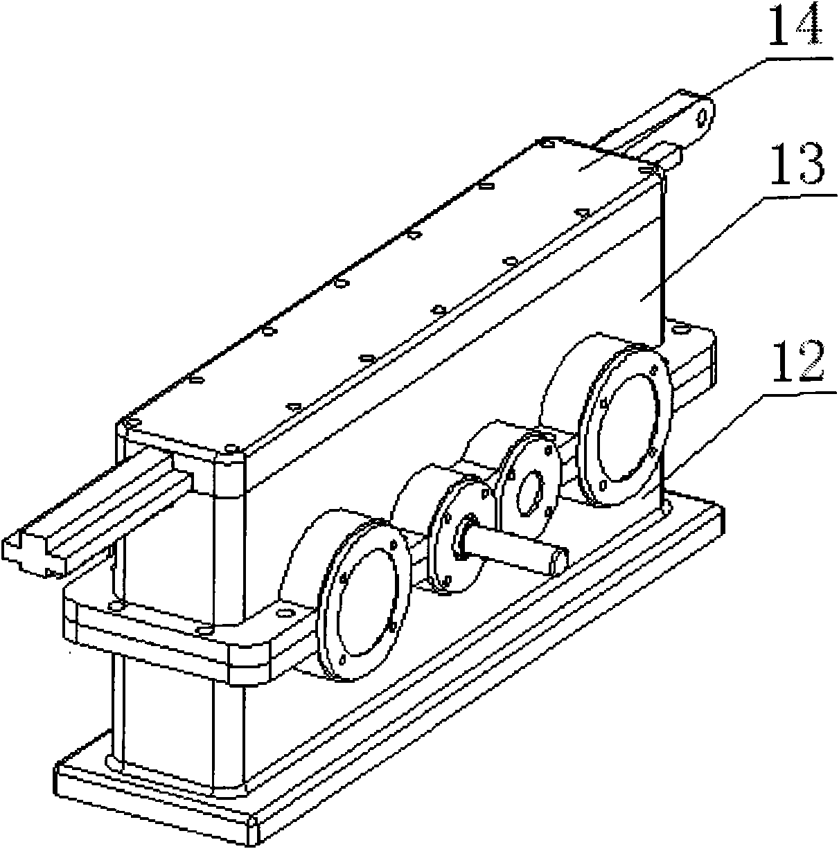
[0022] Such as Figures 1 to 5 As shown, a transmission speed change device includes a reciprocating gear 1, a right shifting half gear 2, a left shifting half gear 11, and an input gear 5. The input gear 5 meshes with the right shifting input gear 3, and the right shifting input gear 3 The right shifting half gear 2 is fixed on the right shifting input shaft 4, the right shifting half gear 2 meshes with the reciprocating gear 1, the reciprocating gear 1 meshes with the left shifting half gear 11, and the left shifting half gear 11 meshes. Move half side gear 11 and left shift input gear 10 and be fixed on the left shift input shaft 9, described left shift input gear 10 meshes with fall wheel 7, and described fall wheel 7 meshes with described input gear 5; Said right shift half side The size of the gear 2 and the le...


PUM


Abstract

The invention discloses a transmission speed change device, which comprises a reciprocating gear, a right-shift half gear, a left-shift half gear, and an input gear. The input gear is meshed with a right-shift input gear; the right-shift input gear and the right-shift half gear are fixed on a right-shift input shaft; the right-shift half gear is meshed with the reciprocating gear; the reciprocating gear is meshed with the left-shift half gear; the left-shift half gear and a left-shift input gear are fixed on a left-shift input shaft; the left-shift input gear is meshed with an idler wheel; and the idler wheel is meshed with the input gear. The right-shift half gear and the left-shift half gear are same in size, have a toothed radian of 180 DEG, have a phase difference of 180 DEG and are not simultaneously meshed with the reciprocating gear; the right-shift input gear and the left-shift input gear are same in type; and the input gear and the idle wheel are same in type. The transmission speed change device has the characteristics of stable operation, constant speed, uniform load and precise transmission, and is applicable to reciprocating movement of various machines.

Description

technical field [0001] The invention relates to the field of mechanical transmission, in particular to a reciprocating linear motion transmission mechanism used in planers, robots, electric sewing machine heads and the like. Background technique [0002] Reciprocating linear motion has a wide range of applications in national production, such as the feed motion and cutting motion of various processing machine tools, reciprocating electric tools, punching machines in mold sheet metal, etc. At present, the mechanisms that realize reciprocating motion mainly include: crank slider mechanism or guide rod mechanism, cam mechanism, linear motor, two-way screw, etc. in the planar linkage mechanism. The connecting rod mechanism is widely used because of its simple structure and easy processing, but its transmission route is long, and it is easy to generate large error accumulation; Due to the large dynamic load, it is not suitable for high-speed movement. [0003] Although the dyna...

Claims


Application Information

Patent Timeline
IPC IPC(8): F16H19/04
Inventor 乔海祥何友光刘日强周国辛华任英峰袁盛杰董爽陈勇卿新华
Owner 乔海祥
Why Eureka
Try Eureka