RS485 bus interface circuit

A RS485B, bus interface technology, applied in the field of RS485 bus communication, can solve the problems of communication rate and anti-interference performance that cannot meet the needs of communication transmission, and achieve the effect of increasing power

Inactive Publication Date: 2011-08-31
QUANZHOU WANHUA TECH
View PDF5 Cites 8 Cited by
  • Summary
  • Abstract
  • Description
  • Claims
  • Application Information

AI Technical Summary

Problems solved by technology

Most of the existing RS485 communication interface schemes are realized by using conventional RS485 interface chips. For those using conventional RS485 interface chips, because the communication signal output power

Method used


Image

  • RS485 bus interface circuit
  • RS485 bus interface circuit

Examples


Embodiment approach 1

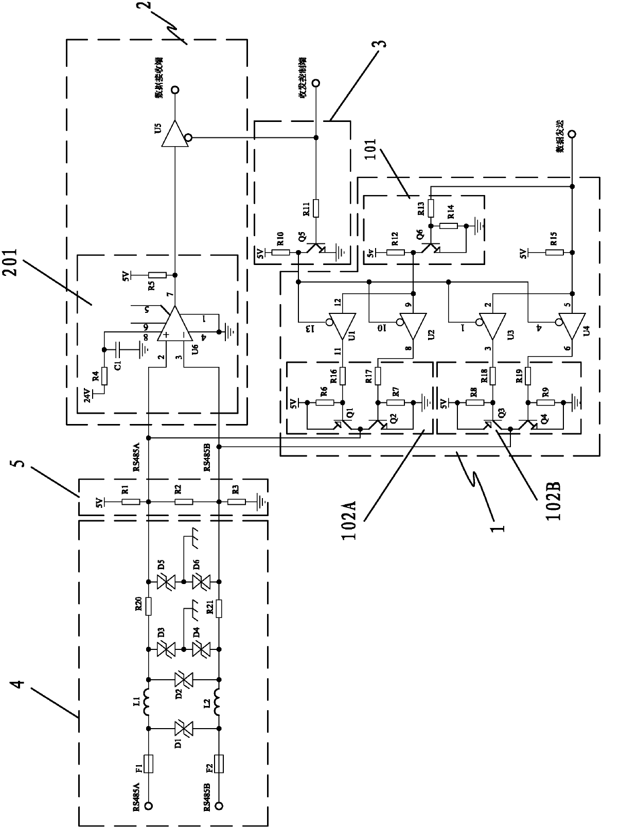
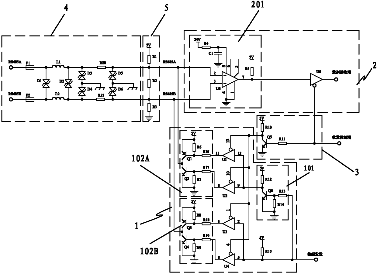
[0019] Embodiment 1: The tri-state gates U1-U5 of the differential signal sending circuit 1 and the differential signal receiving circuit 2 are all high-level control enabled tri-state gates, and the triode of the data sending and receiving control circuit 3 is inverted The output terminal of the transistor is connected to the enable control terminal of the high-level control enable tri-state gate U5 of the differential signal receiving circuit 2, and the input terminal of the triode inverter is connected to the four terminals of the differential signal transmitting circuit 1. High-level control enables the enable control terminals of the tri-state gates U1-U4; although this embodiment can realize the data transmission and reception control, however, the output terminal of the triode inverter has a high driving capability, and it is connected to the differential signal receiving circuit 2 The high-level control enables the enable control terminal of the tri-state gate U5, and t...

Embodiment approach 2

[0020] Embodiment 2: In this embodiment, the tri-state gates U1-U4 of the differential signal sending circuit 1 are all high-level control enabled tri-state gates, and the tri-state gate U5 of the differential signal receiving circuit 2 It is a tri-state gate enabled by low-level control. At this time, the data transceiver control circuit is directly connected to the tri-state gate U1-U4 of the high-level control enable in the differential signal transmission circuit 1 and The control enable end of the tri-state gate U5 enabled by low level control in the differential signal receiving circuit 2; although this embodiment can realize the data transceiver control function, its data transceiver end is connected to 5 tri-state gates U1- The control enabling end of U5 is prone to misoperation of the sending and receiving control due to insufficient driving capability of the data sending and receiving end.

Embodiment approach 3

[0021] Embodiment 3: This embodiment is a preferred embodiment of the present invention, wherein, the tri-state gates U1-U5 of the differential signal sending circuit 1 and the differential signal receiving circuit 2 are all tri-state gates enabled by high-level control. state gate, the output terminal of the triode inverter of the data sending and receiving control circuit 3 is connected to the enable control terminal of the high-level control enabling tri-state gate U5 of the differential signal receiving circuit 2, and the input of the triode inverter The four high-level control terminals of the differential signal transmission circuit 1 enable the enable control terminals of the tri-state gates U1-U4; like this, when the transceiver control terminal controls data reception with a high level, the high level The signal passes through the inversion of the triode inverter, and outputs a low level to control the conduction of the three-state gates U1, U2, U3, and U4, and also im...


PUM


Abstract

The invention relates to the technical field of communication of RS485 buses, in particular to an RS485 bus interface circuit. The technical scheme is that: a differential signal transmission circuit section of an RS485 interface consists of a triode inverter, two sets of push-pull type inverting amplifiers and four triple gates, wherein the output end of the triode inverter is connected to the two push-pull signal input ends of a first set of push-pull type inverting amplifier through a first triple gate and a second triple gate respectively; the output end of the first set of push-pull typeinverting amplifier is connected with a first differential signal wire RS485A; and a direct signal of a second set of push-pull type inverting amplifier is communicated with the input end of the triode inverter and a second differential signal wire RS485B. Through the two sets of push-pull type inverting amplifiers, an RS485 differential signal can be output, and the power of an output signal is effectively improved, so that the communication distance in the scheme can reach 2,000 m, 64 transceivers can be hung, and the communication rate can reach 9,600 bps.

Description

technical field [0001] The invention relates to the technical field of RS485 bus communication, in particular to an RS485 bus interface circuit. Background technique [0002] RS485 is a widely used communication protocol. Its main feature is to transmit data with differential electrical signals, that is, on paired communication lines, information is transmitted by using a pair of symmetrical signals of equal size and opposite polarity. , this kind of data transmission scheme can effectively resist external common mode interference, and has strong anti-interference ability. Most of the existing RS485 communication interface schemes are realized by using conventional RS485 interface chips. For those using conventional RS485 interface chips, the communication signal output power of the chip is designed in a standardized manner. Neither the anti-interference performance nor the number of transceivers can meet the communication transmission requirements of these special occasion...

Claims


Application Information

Patent Timeline
IPC IPC(8): G06F13/40
Inventor 傅锦青
Owner QUANZHOU WANHUA TECH
Why Eureka
Try Eureka