Check patentability & draft patents in minutes with Patsnap Eureka AI!

Asynchronously-started permanent magnet synchronous motor rotor

A technology of asynchronous start and permanent magnet synchronization, which is applied in the direction of synchronous machines, synchronous machine parts, electrical components, etc., can solve the problems of long production cycle, increased motor cost, easy to fly off, etc., and achieve huge economic and social benefits, Reduce magnetic flux leakage and hysteresis loss, the effect of cumbersome process

Inactive Publication Date: 2011-08-31
王乃兵
View PDF0 Cites 3 Cited by
  • Summary
  • Abstract
  • Description
  • Claims
  • Application Information

AI Technical Summary

Problems solved by technology

Especially in the existing permanent magnet synchronous motor, there is an unreasonable rotor structure and immature technology. On the basis of the ordinary asynchronous motor rotor, the magnetic steel is slotted symmetrically inside the squirrel cage, which greatly reduces the mechanical strength of the rotor and shortens the service life. And the magnetic steel has defects such as large flux leakage in the rotor core, and some rotors are surface-mounted with magnetic steel, which is easy to fly off when used. When there is really no way to do it, it is too simple to set holes on the magnetic steel and fix it with screws. , and easy to demagnetize, etc., and cannot be generalized
There are also some permanent magnet motor manufacturers who install a white rust steel magnetic isolation sleeve on the motor shaft on the circumference of the magnetic isolation sleeve, and use screw rods to install magnetic poles and magnetic steel. There are axial fixing methods and radial fixing methods. The starting cage made of strips greatly increases the cost of the motor
And waste work and waste time, the production cycle is longer, in short, none of the messy structures can achieve practical value and many other shortcomings

Method used


Image

  • Asynchronously-started permanent magnet synchronous motor rotor
  • Asynchronously-started permanent magnet synchronous motor rotor
  • Asynchronously-started permanent magnet synchronous motor rotor

Examples


Embodiment Construction

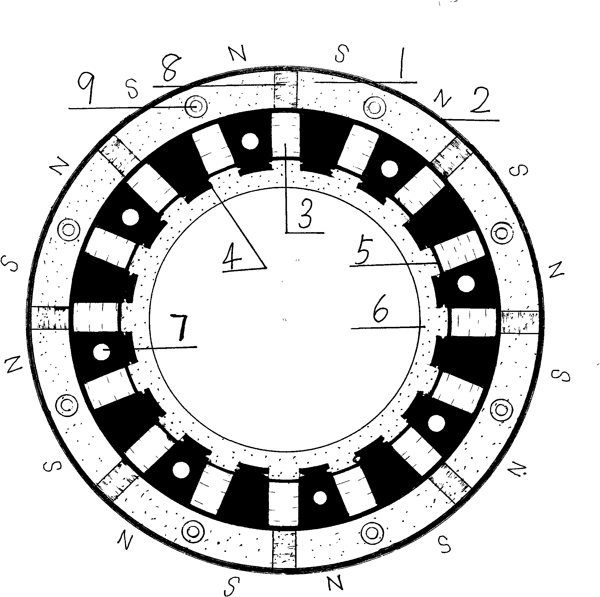
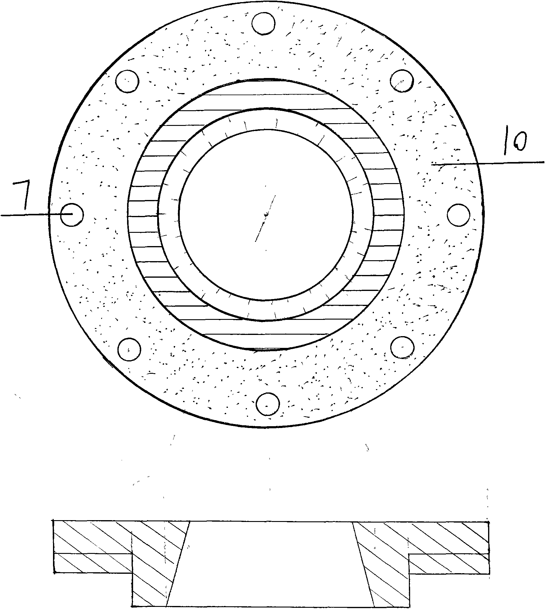
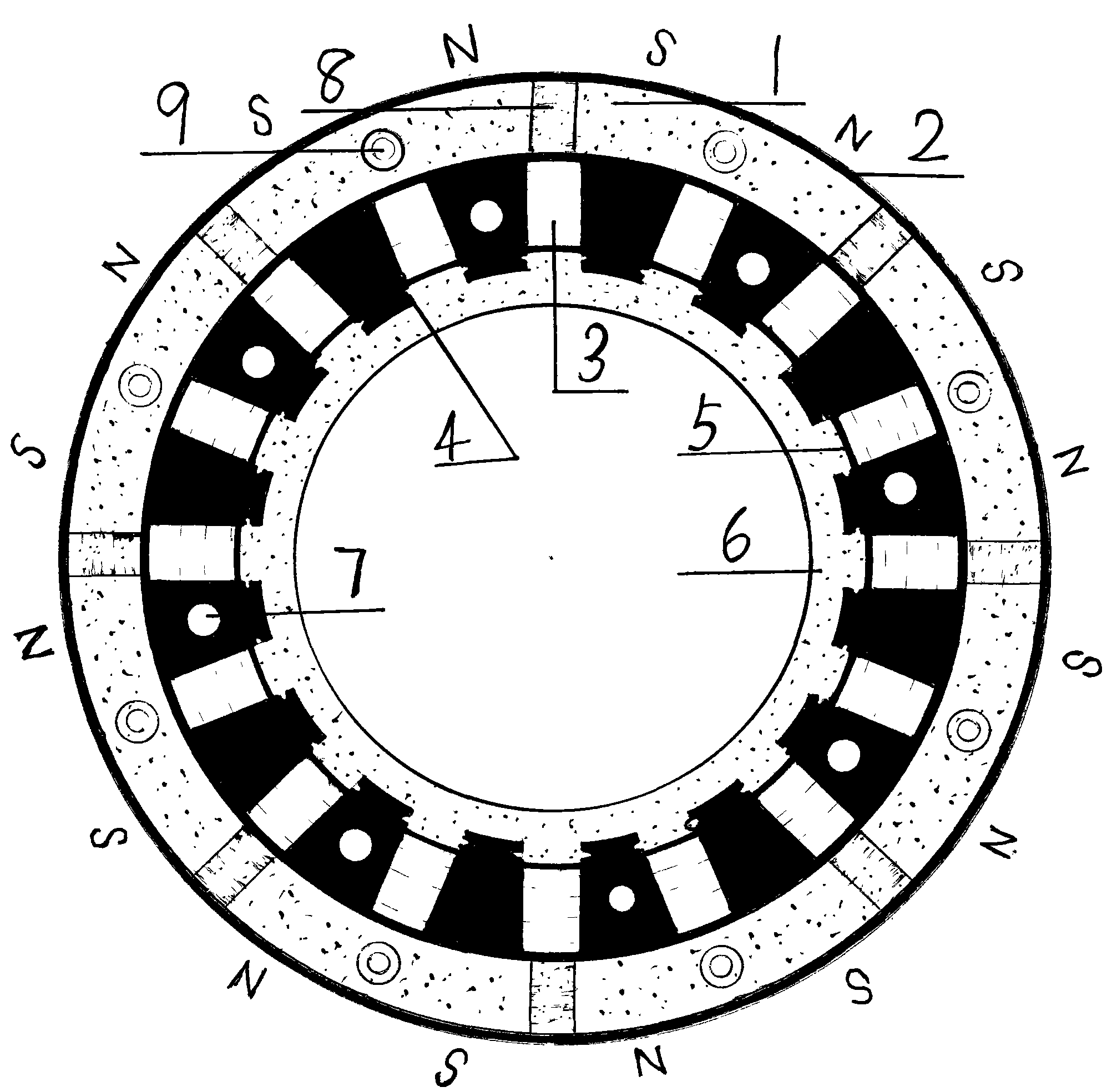
[0010] The present invention will be further described below in conjunction with drawings and embodiments. figure 1 It is the structural diagram of the rotor of the asynchronous starting permanent magnet synchronous motor of the present invention. The process method and aluminum injection of the asynchronous starting cage 1 in the figure are the same as those of the ordinary asynchronous motor rotor. The aluminum alloy cylinder 6 is generally cast together after preheating the rotor core, and the laminated rotor The core 2 is made of laminated steel plates with excellent magnetic permeability, and the magnetic steel

[0011] The magnetic steel 3 is made of high-performance N35 NdFeB permanent magnet material. The rotor bracket is made of 45# steel plate to facilitate ventilation and heat dissipation. Ventilation holes are left on the rotor bracket to effectively reduce the weight of the rotor and ventilation and heat dissipation. The shaft is also made of 45# steel. In order t...


PUM


Abstract

The invention relates to the field of motors, in particular to an asynchronously-started permanent magnet synchronous motor rotor, which mainly comprises an asynchronous starting cage, a hollow laminated rotor core, magnetic steel, a rotor bracket, a rotating shaft and fan blades, wherein the laminated rotor core comprises a shaft hole with a diameter which is many times that of a rotating shaft, and is arranged in a way of off-axis with the rotating shaft; the inner circumference of the rotor core is radially provided with a magnetic steel slot; the core at an opening of the magnetic steel slot is provided with a fixing groove; the opening of the magnetic steel slot is provided with a magnetic-shielding magnetic bridge; each tooth of an internal diameter of the rotor core and the fixing groove are impregnated and cast in a cylinder made from a non-magnetic conducting material; and bolt fixing holes are punched in poles. Compared with the prior art, the asynchronously-started permanent magnet synchronous motor rotor has the advantages of extremely low cost, super-light weight, hollowness, higher suitability for being made from a permanent magnetic material with a relatively smaller volume, reduction in magnetic leakage and hysteresis loss, extremely high reliability and applicability and the like, and effectively takes the place of the prior art with high cost.

Description

technical field [0001] The invention relates to a synchronous motor, and is particularly suitable for an asynchronous start permanent magnet synchronous motor rotor with high efficiency and energy saving such as used in the oilfield textile industry. Background technique [0002] Existing three-phase motors or three-phase permanent magnet synchronous motors have high energy consumption, especially ordinary asynchronous motors with relatively low efficiency and power factor, large no-load and light-load currents, and reactive excitation losses, which waste our precious energy, and increase user costs. Especially in the existing permanent magnet synchronous motor, there is an unreasonable rotor structure and immature technology. On the basis of the ordinary asynchronous motor rotor, the magnetic steel is slotted symmetrically inside the squirrel cage, which greatly reduces the mechanical strength of the rotor and shortens the service life. And the magnetic steel has defects s...

Claims


Application Information

Patent Timeline
Patent Type & Authority Applications(China)
IPC IPC(8): H02K21/02H02K1/27H02K21/46
Inventor 王乃兵
Owner 王乃兵
Features
  • R&D
  • Intellectual Property
  • Life Sciences
  • Materials
  • Tech Scout
  • Unparalleled Data Quality
  • Higher Quality Content
  • 60% Fewer Hallucinations
Learn More