
Dynamic frequency offset correction method and coherence optical time-domain reflectometer system

A technology of time domain reflectometer and coherent light, which is applied in the field of optical fiber communication, can solve problems such as influence and detection effect, and achieve the effect of reducing requirements and improving optical coherent detection performance

Inactive Publication Date: 2014-01-08
深圳市联创知识产权服务中心
View PDF3 Cites 0 Cited by
  • Summary
  • Abstract
  • Description
  • Claims
  • Application Information

AI Technical Summary

Problems solved by technology

However, the existing technology has the following disadvantages: due to the high requirements on the line width of the light source in COTDR, the adjustment of the frequency of the light source will affect the line width of the light source, therefore, it will affect the detection effect

Method used


Image

  • Dynamic frequency offset correction method and coherence optical time-domain reflectometer system
  • Dynamic frequency offset correction method and coherence optical time-domain reflectometer system
  • Dynamic frequency offset correction method and coherence optical time-domain reflectometer system

Examples


Embodiment Construction

[0040] In order to make the purpose, technical solutions and advantages of the embodiments of the present invention clearer, the technical solutions in the embodiments of the present invention will be clearly and completely described below in conjunction with the drawings in the embodiments of the present invention. Obviously, the described embodiments It is a part of embodiments of the present invention, but not all embodiments. Based on the embodiments of the present invention, all other embodiments obtained by persons of ordinary skill in the art without making creative efforts belong to the protection scope of the present invention.

[0041] The embodiment of the present invention detects the frequency offset of the laser and corrects the corresponding frequency offset, thereby eliminating the influence of the frequency drift of the laser output by the laser, reducing the bandwidth requirements of the communication system, and improving Performance of a coherent optical ti...


PUM


Abstract

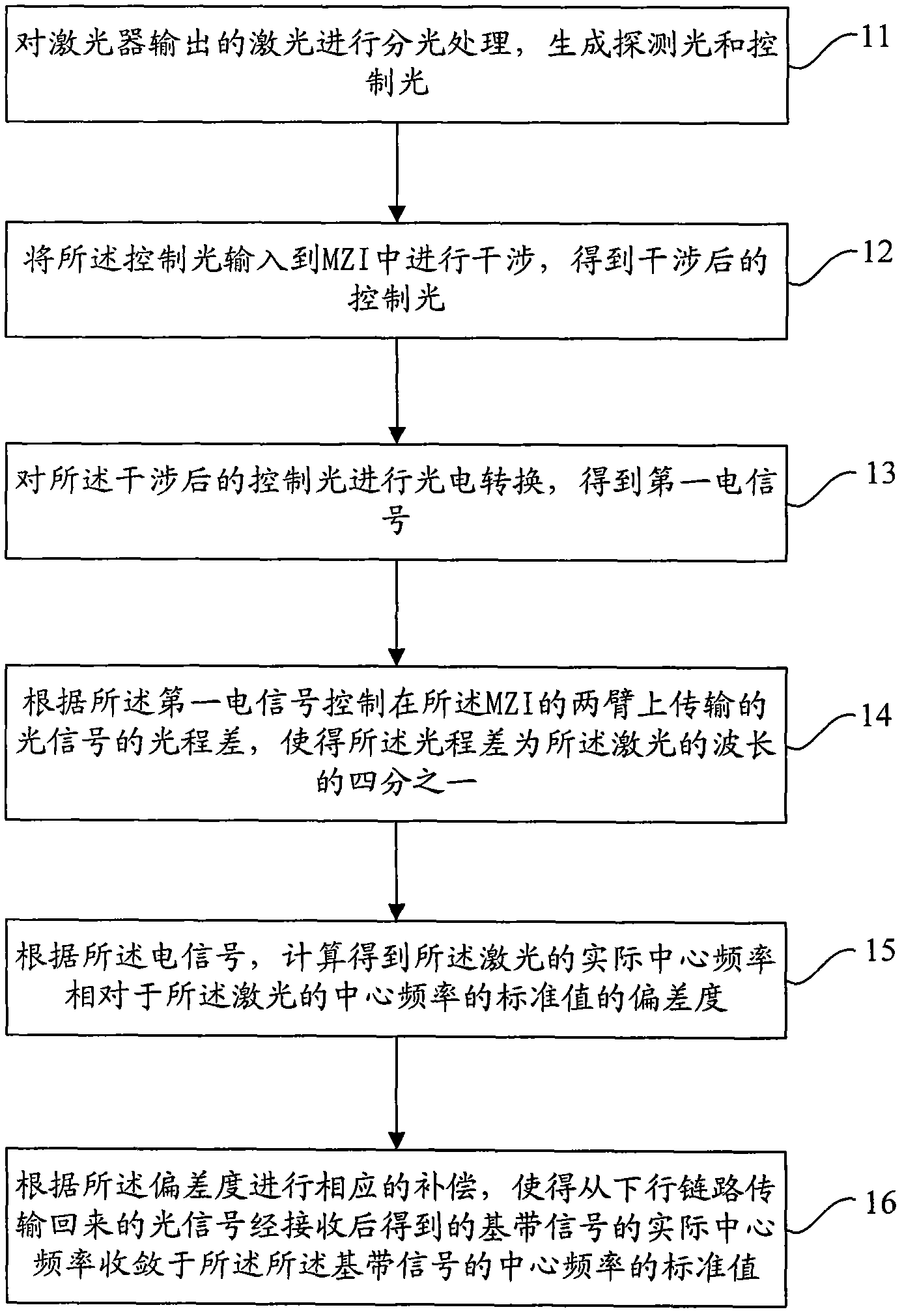
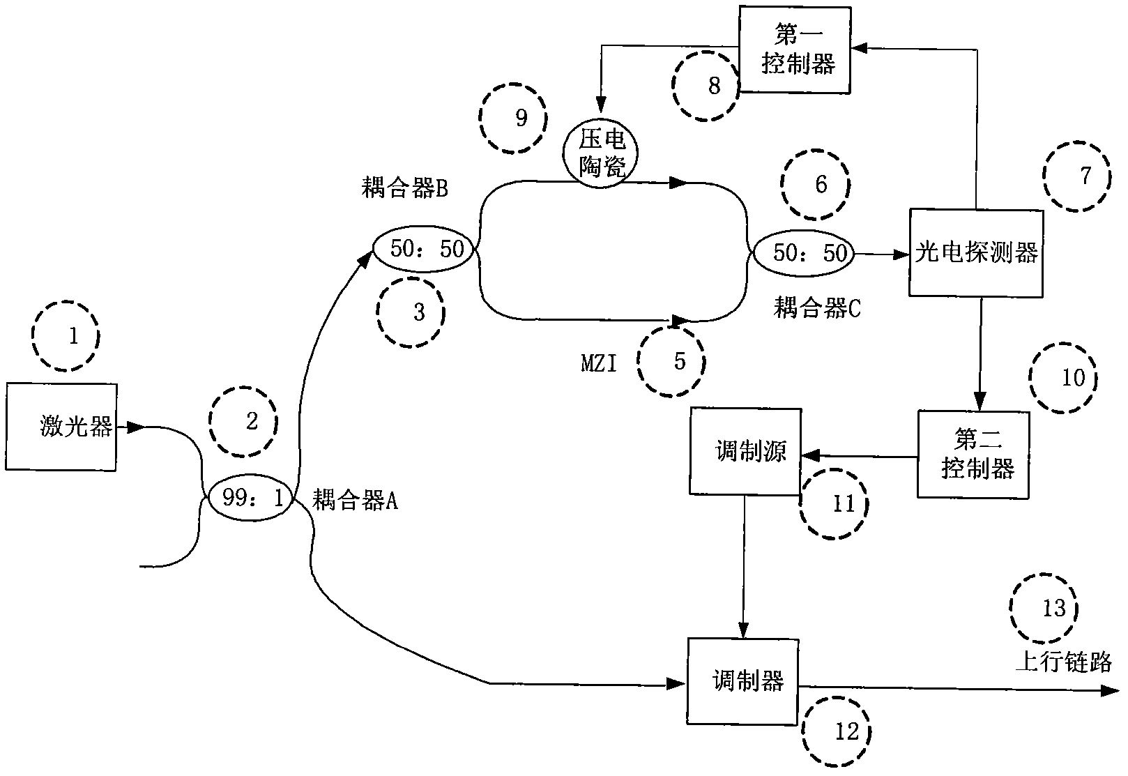
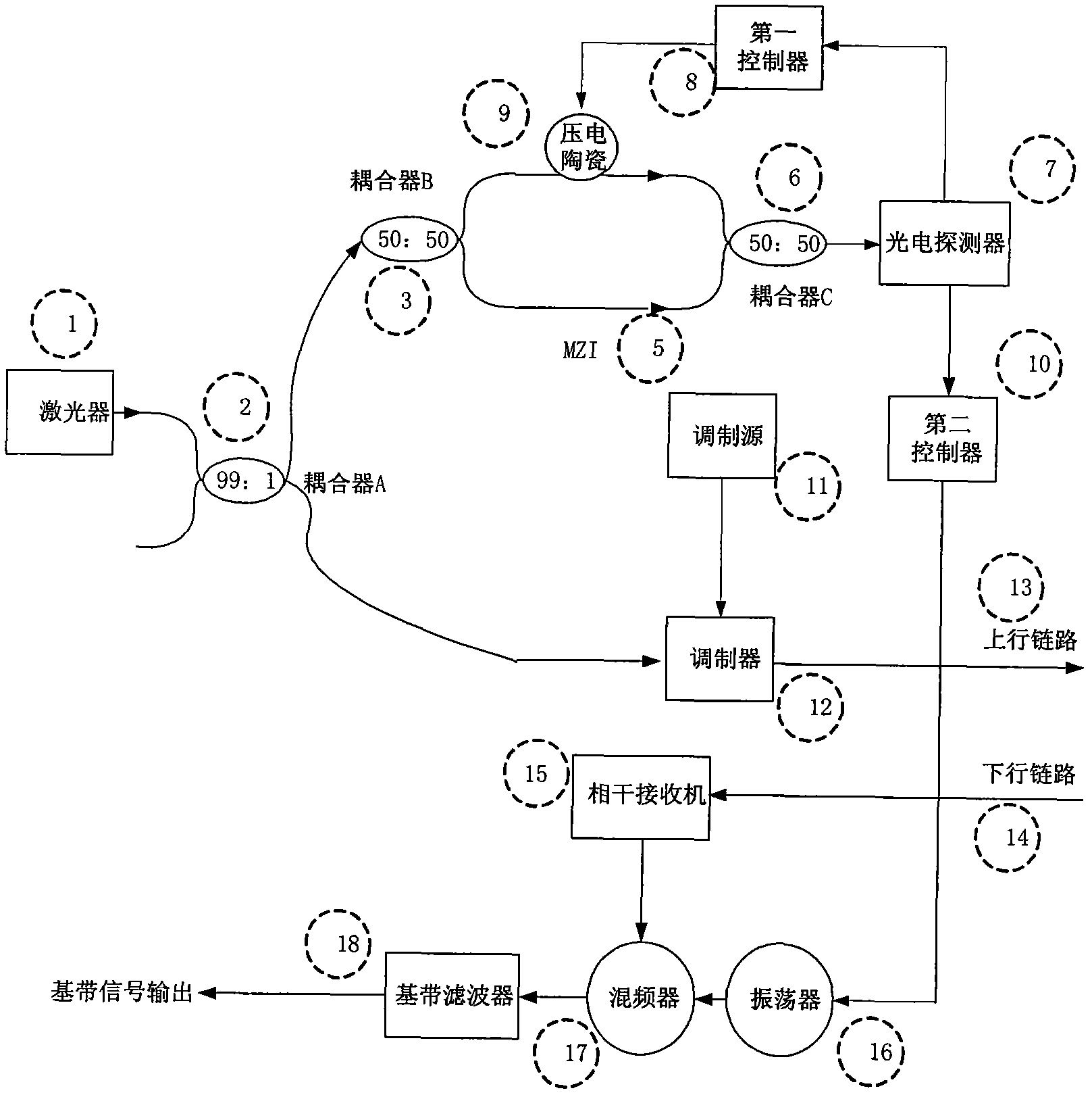
A dynamic frequency deviation correction method and a coherence optical time-domain reflectometer system are disclosed. The method comprises: splitting a laser beam output by a laser, to generate probe light and control light; inputting the control light into an MZI for interference, and performing photoelectric conversion on the interfered control light to obtain a first electric signal; controlling, according to the first electric signal, an optical path difference between optical signals transmitted on two arms of the MZI, so that the optical path difference is a quarter of the wavelength of the laser beam; calculating, according to the first electric signal, a deviation degree of an actual center frequency of the laser beam relative to a standard value of the center frequency of the laser beam; and performing corresponding compensation according to the deviation degree. In the present invention, the laser beam output by the laser is split into the probe light and control light, and the deviation degree of the actual center frequency of the laser beam relative to the standard value of the center frequency of the laser beam is calculated according to the control light; corresponding correction control is performed, according to the deviation degree, on the laser beam output by the laser, so as to improve optical coherent detection performance.

Description

technical field [0001] The invention relates to the technical field of optical fiber communication, in particular to a dynamic frequency offset correction method and a coherent optical time domain reflectometer system. Background technique [0002] With the development of optical fiber communication technology, the optical fiberization of the network has always been one of the main trends in network development. The submarine optical cable is a very important part of the network optical fiber, and the real-time monitoring of the long-distance submarine optical cable has also become an important content of network maintenance. [0003] When testing submarine optical cables, a coherence optical time-domain reflectometer (hereinafter referred to as COTDR) is used for testing. In the COTDR system, due to the need to detect ultra-long-distance laser reflection signals, the laser is in Frequency drift during the measurement will affect the receiver receiving frequency. In order ...

Claims


Application Information

Patent Timeline
Patent Type & Authority Patents(China)
IPC IPC(8): H04L27/227H04B10/07H04B10/61H04B10/071
CPCH04B10/071G01M11/3109
Inventor 冯志勇王顺张旭苹张益昕
Owner 深圳市联创知识产权服务中心
Learn More