Method and apparatus for towing offshore wind turbines

A technology of wind turbines and buoyancy, which is applied in the assembly of wind turbines, the configuration of installing/supporting wind turbines, wind turbines, etc., which can solve the problems of increasing the cost of transporting wind turbines, limiting route selection and installation locations, etc.

Active Publication Date: 2011-08-31
海维德公司
View PDF9 Cites 5 Cited by
  • Summary
  • Abstract
  • Description
  • Claims
  • Application Information

AI Technical Summary

Problems solved by technology

It will be appreciated that employing such a vessel increases the cost of transporting the wind turbine and that the size of the vessel may also limit routing options and installation locations

Method used


Image

  • Method and apparatus for towing offshore wind turbines
  • Method and apparatus for towing offshore wind turbines
  • Method and apparatus for towing offshore wind turbines

Examples


Embodiment Construction

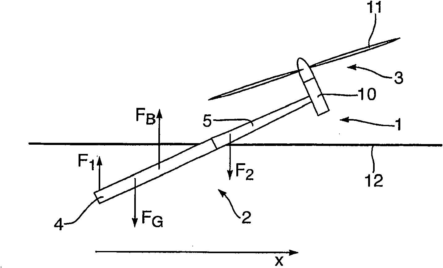
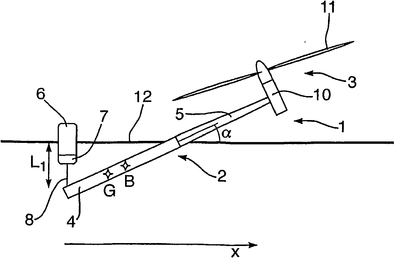
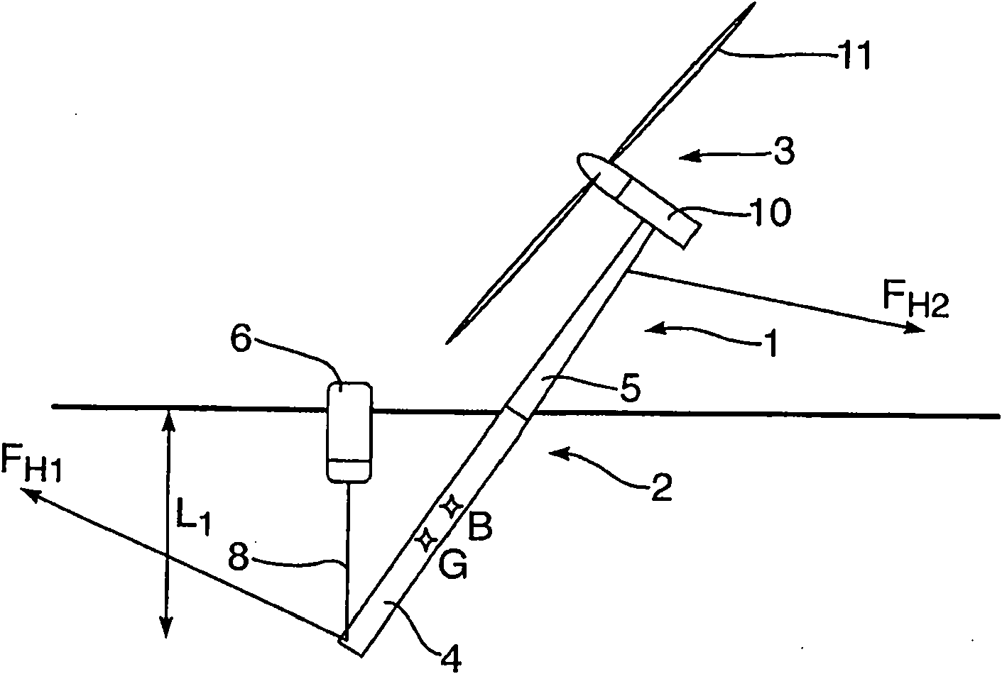
[0030] figure 1 The forces acting on a preferred embodiment floating wind turbine (hereinafter "wind turbine") 1 in a tilted position are shown. The wind turbine 1 comprises a support structure 2 and a wind turbine generator 3 . The support structure 2 comprises a lower support structure 4 and a tower 5 . The wind turbine generator 3 comprises a nacelle 10 and a rotor 11 . f G is the gravity of wind turbine 1. f B is the buoyancy of wind turbine 1.

[0031] To keep the wind turbine 1 in a tilted position, an upwardly directed force F is required 1 . like figure 1 Shown, F 1 It should act from a position on the lower support structure 4 below the center of gravity of the wind turbine 1 . Optionally, a downwardly directed force F acting above the center of buoyancy 2Can also be applied to wind turbines 1 .

[0032] The inclined floating position of the wind turbine 1 should be stable. This requires a stable balance of forces and moments in a vertical plane passing t...


PUM


Abstract

A method of moving a floating wind turbine (1) relative to a body of water, the floating wind turbine (1) having a buoyant body with a nacelle at the upper end thereof. The method comprises floating the floating wind turbine (1) in the body of water, and towing the floating wind turbine (1) whilst holding the buoyant body in an inclined position, whereby the nacelle is held clear of the water. As the wind turbine (1) is held in an inclined position, it can be towed through regions of shallower water than if it were in a vertical position.

Description

technical field [0001] The present invention relates to the field of floating wind turbines, and in particular to a method and arrangement for moving a floating wind turbine off-shore. Background technique [0002] As employed herein, the term "floating wind turbine" refers to the type of wind turbine structure designed to float in a body of water when in use. A conventional floating wind turbine comprises a buoyant body having at its upper end a nacelle housing a generator and other components, and a rotor. The body is generally long and approximately cylindrical in shape. [0003] Offshore floating wind turbines are very large structures, the body is typically 100-200 meters in length and the rotor blades are in the range of 40-70 meters long. They are assembled onshore or in protected waters, and moving them out to the desired location at sea is a significant challenge. [0004] One method is to tow them through the body of water to their installation site while floati...

Claims


Application Information

Patent Timeline
Patent Type & Authority Applications(China)
IPC IPC(8): F03D1/00B63B21/00
CPCF03D1/001Y02E10/72Y02E10/726Y02E10/728F03D1/005B63B21/00Y02E10/721F03D13/10F03D13/40Y02E10/727F03D13/20B63B35/44B63B75/00F05B2240/95
Inventor F·G·尼尔森
Owner 海维德公司
Why Eureka
Try Eureka