
Blade type hydraulic motor with rocker arm structure

A hydraulic motor and vane type technology, applied in the field of vane type hydraulic motor, can solve the problems of reduced hydraulic motor efficiency, irregular gap leakage, difficult processing and assembly, etc., and achieve the effects of eliminating lag, reducing internal leakage and improving efficiency

Active Publication Date: 2011-09-07
宁波恒通诺达液压股份有限公司
View PDF11 Cites 15 Cited by
  • Summary
  • Abstract
  • Description
  • Claims
  • Application Information

AI Technical Summary

Problems solved by technology

[0003] 1. The materials of the blades and the stator are both metal, and the blades are in direct contact with the inner surface of the stator. The blades are close to the surface of the stator by the thrust of the spring at the bottom. In addition to rotating with the rotor, they are affected by the inner curved surface of the stator. Pushing, the blade will reciprocate along its normal direction. Under the thrust of the spring, the blade will have pressure on the stator, and the long-term use will cause serious wear, which will not only cause heat, but also cause internal leakage due to irregular gaps caused by long-term wear. One of the main reasons, resulting in a reduction in the efficiency of the hydraulic motor
[0004] 2. Vane hydraulic motors are often used in occasions with low speed, high torque, and frequent direction changes, and the high-speed performance is not good
This structure requires that the inner surface of the stator must be circular, so it can only be used for single-acting vane hydraulic motors, and the output torque is small. The ball joints on the follower cylinder and the rotor are very difficult to process and assemble, and the cost is high. The moving cylinder is thicker and has a large inertia when rotating, so it is not suitable for occasions with frequent speed changes and direction change requirements

Method used


Image

  • Blade type hydraulic motor with rocker arm structure
  • Blade type hydraulic motor with rocker arm structure
  • Blade type hydraulic motor with rocker arm structure

Examples


Embodiment 1

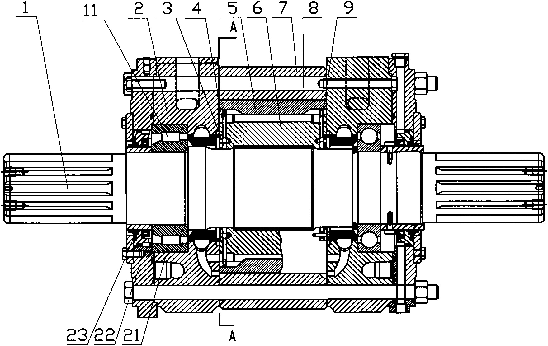
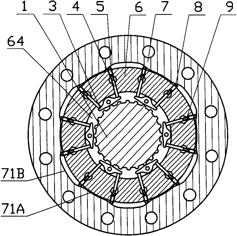
[0034] Embodiment one: if figure 1 As shown, a six-action vane hydraulic motor includes a rotating shaft 1 , a casing 2 , a rotor 6 , and a stator 7 . The housing 2 is composed of an oil distribution plate 21, an end cover 22 and a seal 23. The oil distribution plate 21 has an oil circuit and an inlet and outlet of the oil circuit, and a bearing 11 is installed between the oil distribution plate 21 and the end cover 22, and the bearing Seal 23 is also installed beside 11 to carry out leakproof and dustproof protection. End cover 22, oil distribution plate 21 and stator 7 are connected with 12 bolts. A rotor 6 is installed in the stator 7, and the rotor 6 is splined to the rotating shaft 1.

[0035] The inner surface of the stator 7 is an inner curved surface 71, and the surface of the rotor 6 has 12 blade grooves 61. Such as image 3 As shown, the cross section of the vane slot is U-shaped, and the vane 5 is installed. There is a through hole 62 communicating with it on bo...

Embodiment 2

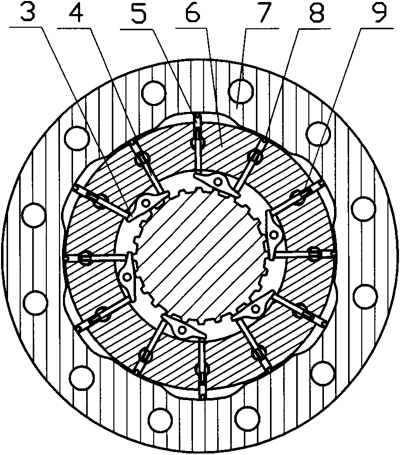
[0043] Embodiment 2: In order to further increase the torque of the hydraulic motor and improve the performance of the hydraulic motor, especially the stability of the low-speed operation, the number of blades on the rotor can be doubled. Such as Figure 5 , Image 6 As shown, in addition to being the same as the first embodiment, the circular groove 64 of the rotor 6 is directly connected with a set of rocker beams 3 (6 on one side and 12 in total) with pin shafts on the circular groove 64 of the rotor 6; Connect an annular backing plate 65 with screws on the circular groove 64, and the bottom surface of the annular backing plate 65 and the circular groove 64 on the rotor is parallel, and a set of rocker beam 3 ′ is installed on the 65 inner sides of the annular backing plate. Correspondingly, the number of vane grooves 61 on the rotor 6 is doubled, and the position corresponding to the rocker beam 3' in the vane slots is provided with a through hole and a circular cavity, a...


PUM


Abstract

The invention discloses a blade type hydraulic motor with a rocker arm structure. The hydraulic motor comprises an end cover, an oil distribution disc, a stator, a rotor and a rotating shaft, wherein the rotor is connected with the rotating shaft by a spline; a plurality of blade grooves are uniformly formed on the rotor; two layers of rocker arm beams are arranged in circular grooves at the two ends of the rotor, each layer comprises a plurality of rocker arm beams, holes are formed in the centers of the rocker arm beams; pin shafts pass through the holes to rotationally connect the rocker arm beams with the rotor; circular cavities are formed at the two ends of each blade groove; through holes which are intersected with the circular cavities along the radial direction are formed below the circular cavities; pull rods and springs are arranged in the through holes sequentially; the bottom surfaces of the pull rods are contacted with the arms of the rocker arm beams; blades are arranged in the blade grooves; the bottom ends of the blades are contacted with the springs; the springs are positioned in the circular cavities; an oil circuit is communicated with the circular cavities; grooves are formed on the tops of the blades; and blade heads are inserted into the grooves, are tightly matched with the blades, are higher than the tops of the blades and are contacted with the inner curve surface of the stator. The hydraulic motor has high sealing performance between the blades and the stator, small abrasion during rotation, higher efficiency and longer service life.

Description

Technical field [0001] The invention relates to a vane type hydraulic motor, in particular to a vane type hydraulic motor with a rocker arm structure. Background technique [0002] A traditional vane hydraulic motor has a structure such as that shown in CN200420070363.4 "a through-hole hydraulic motor" and CN200920102511.9 "vane hydraulic motor". The vane and spring are arranged in the vane chute of the rotor. The rotor is installed in the stator, and the rotating shaft and the rotor are splined. There are two problems with this structure: [0003] 1. The materials of the blades and the stator are both metal, and the blades are in direct contact with the inner surface of the stator. The blades are close to the surface of the stator by the thrust of the spring at the bottom. In addition to rotating with the rotor, they are affected by the inner curved surface of the stator. Pushing, the blade will reciprocate along its normal direction. Under the thrust of the spring, the b...

Claims


Application Information

Patent Timeline
Patent Type & Authority Applications(China)
IPC IPC(8): F01C1/344F01C21/08F03C2/00
Inventor 杨钊徐玮
Owner 宁波恒通诺达液压股份有限公司
Learn More