Back-falling type rope pull starter

A technology of starter and starting shaft, which is applied to the starting of the engine, the starting device with a manual crank, the starting device with a mechanical power storage, etc., which can solve the problem of large spacing, poor rigidity of nylon material, and inability to restart, etc. problem, to achieve the effect of prolonging the service life

Active Publication Date: 2012-08-01
NANTONG HUANGHAI CHEM MACHINERY
View PDF1 Cites 0 Cited by
  • Summary
  • Abstract
  • Description
  • Claims
  • Application Information

AI Technical Summary

Problems solved by technology

[0005] However, the starting plate and the spring seat of the above-mentioned starter are installed on the starting shaft successively, and the shaft diameter at one end of the starting shaft is placed in the shaft hole of the spring seat, and the other end is suspended in the air. Since the parts of the starter are mostly made of nylon material, nylon The rigidity of the material is poor. In addition, the starting connection parts of the starter are affected by processing conditions such as temperature and pressure during the processing process. At this time, since one end of the starting shaft on which the starting disc is installed is in a suspended state, the tension of the pull rope at this end will produce a radial center deviation, which will cause the distance between the spring seat on the starting shaft and the starting disc to be affected by the The force in the opposite direction when the starter rope is pulled out will become larger. In severe cases, the return spring will be stuck in the gap, so that the starter plate will be stuck and cannot rotate freely, resulting in the starter rope not being retracted into the casing in time, resulting in failure to restart the starter. start failure

Method used


Image

  • Back-falling type rope pull starter
  • Back-falling type rope pull starter
  • Back-falling type rope pull starter

Examples


Embodiment Construction

[0034] Embodiments of the present invention will be further described below in conjunction with the above-mentioned drawings.

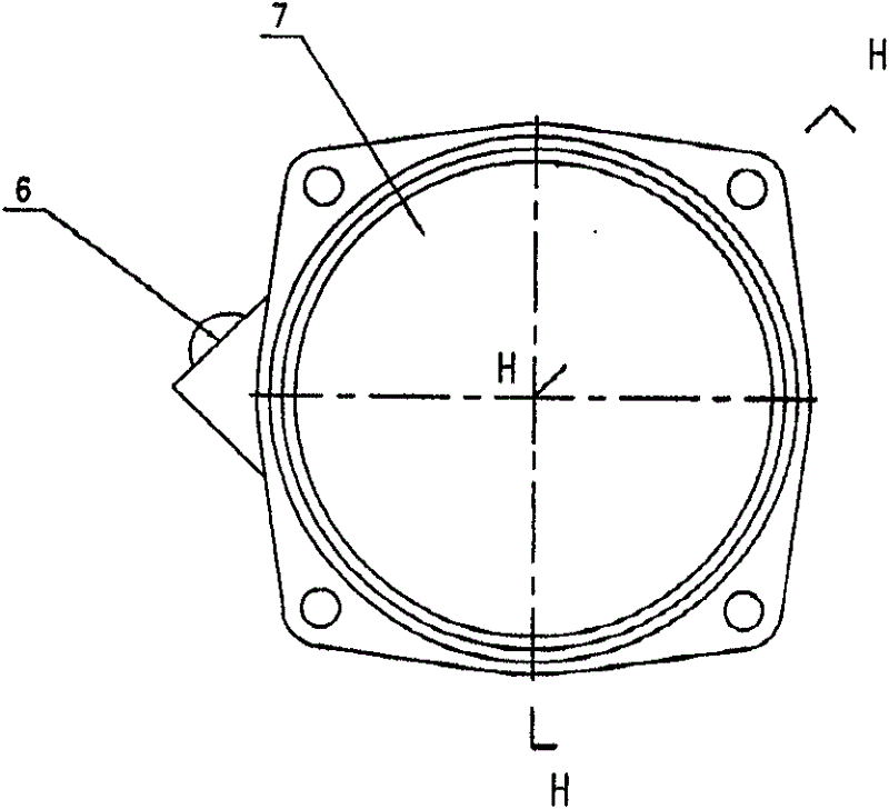
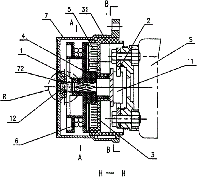
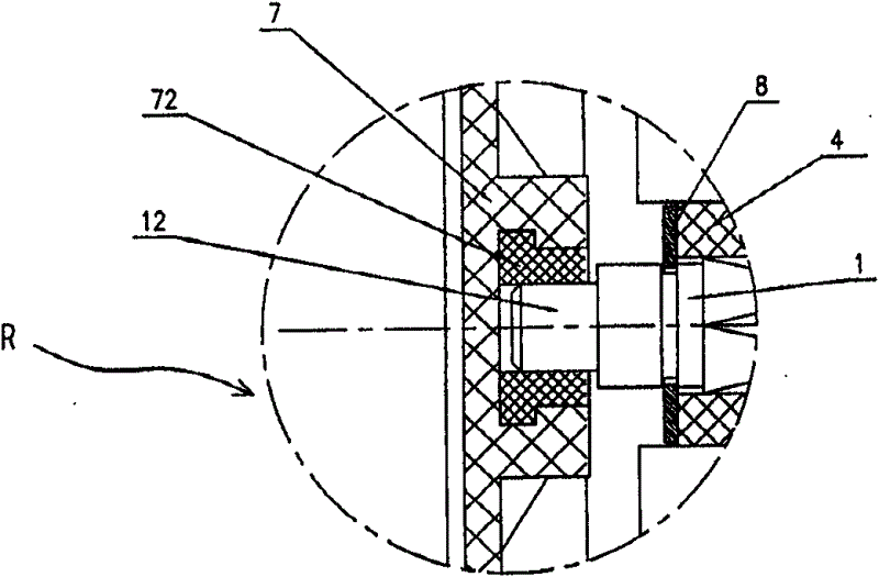
[0035] Such as Figure 1-18 As shown, a fall-back type rope pull starter for gasoline engines below 1E4OF for knapsack spray dusters and lawn mowers is characterized in that it includes a starting shaft 1, a pawl clutch 2, a spring seat 3, a starting Disk 4, back-moving spring 5, stay cord 6, shell 7, starting handle 8. One end of the starting shaft 1 is a one-way ratchet 11, and the other end is a round shaft 12; the pawl clutch 2 is mounted on the rotor S of the gasoline engine and can be engaged or separated from the above-mentioned one-way ratchet 11. Usually, the one-way ratchet and the ratchet The claw clutch part 2 is in the engaged state; the spring seat 3 is mounted on the starting shaft 1 and can rotate on its shaft, and the outer circumferential surface of the spring seat is provided with equidistant bosses 31; Rotate on its shaft; the re...


PUM


Abstract

The invention discloses a back-falling type rope pull starter comprising a starting shaft, wherein one end of the starting shaft is provided with a one-way ratchet wheel, and the other end of the starting shaft is provided with a circular shaft 12; a pawl clutch piece is arranged on a gasoline engine rotor S; a spring seat and a starting disc are arranged on the starting shaft; a boss is arrangedon the outer peripheral surface of the spring seat; a return spring is arranged between the spring seat and the starting disc; the inner end of the return spring is connected with the starting disc, and the outer end of the return spring is connected with the spring seat; a pull rope is wound around the starting disc; one end of the pull rope is connected with the starting disc, and the other endof the pull rope is connected with a starting handle on a shell; the inner side wall of the shell is provided with a groove matched with the boss on the outer periphery of the spring seat; and the center of the bottom of the shell is provided with a shaft sleeve forming a slide fit with the starting shaft. One end of the starting shaft of the starter is arranged in the shaft hole of the spring seat, and the other end of the starting shaft is arranged in the shaft sleeve of the shell, so that if one end of the starting shaft is pulled by the pull rope, axial center displacement is prevented for the starting shaft, the return spring freely retracts, a starting rope of the starter can be withdrawn into the shell in time, the starting process is safe, reliable and smooth, and the service lifeof the starter is improved.

Description

technical field [0001] The invention relates to a starting device for a small gasoline engine, in particular to a starting device for starting a gasoline engine by hand. Background technique [0002] At present, 1E4OF gasoline engine is used for knapsack spray duster on the market. Its starting device includes a starting wheel and a pull rope connected with the gasoline engine rotor. The stay rope on the top drives the above-mentioned rotor to rotate. For example, the Chinese patented technology "fallback type rope pull starter" (patent No. 200620046785.7), the starter includes a starting shaft, and one end of the shaft is provided with a one-way ratchet; A separate pawl clutch; a spring seat mounted on the starting shaft that can rotate on its axis; a starter plate mounted on the starting shaft that cannot rotate on its axis; the outer circumferential surface of the spring seat is provided with bosses at equal distances; The return spring installed between the spring seat...

Claims


Application Information

Patent Timeline
Patent Type & Authority Patents(China)
IPC IPC(8): F02N3/02F02N15/02
Inventor 解禄观
Owner NANTONG HUANGHAI CHEM MACHINERY
Why Eureka
Try Eureka