Flat-shaped liquid-nitrogen and liquid-helium dual-media compatible heat sink device and cooling method thereof

A technology compatible with heat and dual media, applied in the testing of measuring devices, instruments, machines/structural components, etc., can solve problems such as damage to heat sinks, freezing into solids, blockages, etc., to reduce heat radiation, reduce liquid helium consumption, The effect of reducing test costs

Inactive Publication Date: 2012-07-04
BEIHANG UNIV
View PDF0 Cites 0 Cited by
  • Summary
  • Abstract
  • Description
  • Claims
  • Application Information

AI Technical Summary

Problems solved by technology

However, no matter what medium is used, the current heat sink is a single-medium flow channel, and the flow channel of the heat sink can only circulate one heat transfer medium, and cannot switch to another medium.
The main reason is that the freezing point of each refrigeration medium is different. Taking liquid helium and liquid nitrogen as examples, when liquid helium is passed into the flow channel of the heat sink that circulates through the liquid nitrogen, the liquid nitrogen remaining in the flow channel will be frozen. solid, block or even damage the heat sink, so there is no ultra-low temperature heat sink flow channel that shares the two refrigerants of liquid nitrogen and liquid helium before

Method used


Image

  • Flat-shaped liquid-nitrogen and liquid-helium dual-media compatible heat sink device and cooling method thereof
  • Flat-shaped liquid-nitrogen and liquid-helium dual-media compatible heat sink device and cooling method thereof
  • Flat-shaped liquid-nitrogen and liquid-helium dual-media compatible heat sink device and cooling method thereof

Examples


Embodiment Construction

[0033] The present invention will be further described in detail with reference to the accompanying drawings and embodiments.

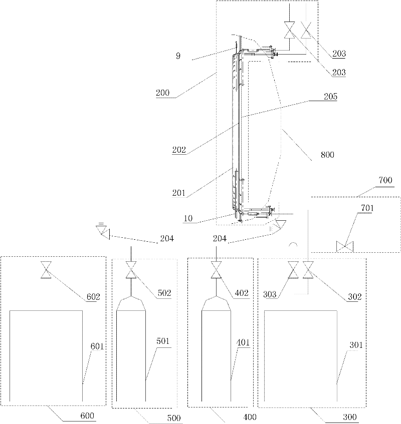
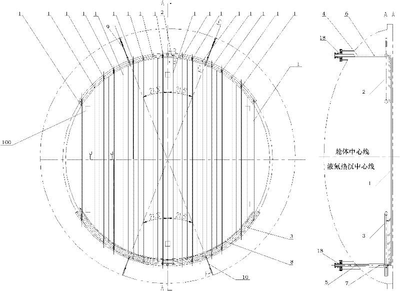
[0034] The flat plate liquid nitrogen and liquid helium dual-medium compatible heat sink device provided by the present invention, such as figure 1 , figure 2 As shown, it includes a heat sink surface resistance temperature sensor 100, a flat heat sink body 200, a liquid nitrogen supply system 300, a gas nitrogen blow-off system 400, a gas helium blow-off system 500, a liquid helium supply system 600 and an auxiliary liquid discharge pipeline 700.

[0035] The liquid nitrogen supply system 300 is composed of a liquid nitrogen storage tank 301 , a liquid nitrogen supply valve 302 for a liquid helium heat sink, and a liquid nitrogen supply valve 303 for a liquid nitrogen heat sink. The liquid nitrogen storage tank 301 is connected to the liquid nitrogen supply valve 302 of the liquid helium heat sink through pipelines, and the liquid nitrogen supply ...


PUM


Abstract

The invention discloses a flat-shaped liquid-nitrogen and liquid-helium dual-media compatible heat sink device and a cooling method thereof, wherein the heat sink device comprises a heat sink body, heat sink surface resistance temperature sensors, an auxiliary drainage pipeline, a liquid nitrogen supply, a gas nitrogen blower, a gas helium blower and a liquid helium supply system; the heat sink body comprises a liquid-nitrogen heat sink, a liquid-helium heat sink and a framework; both the liquid-nitrogen heat sink and the liquid-helium heat sink are flat and round; the liquid-helium heat sinkis arranged at the inner side of the liquid-nitrogen heat sink; the heat sink surface resistance temperature sensors are evenly distributed on the surfaces of the liquid-nitrogen heat sink and the liquid-helium heat sink; the liquid nitrogen supply, the gas nitrogen blower, the gas helium blower, the liquid helium supply system and the auxiliary drainage pipeline are all connected to the inlet ofthe liquid-helium heat sink; and the liquid helium supply system is also connected to the inlet of the liquid-nitrogen heat sink. The cooling method of the heat sink device comprises the following steps of: during the process of working, cooling the liquid-nitrogen heat sink by continuously inletting liquid nitrogen; and cooling the liquid-helium heat sink by firstly inletting liquid nitrogen, and then inletting liquid helium. In the invention, a same heat sink flow passage is shared by the liquid nitrogen and the liquid helium, thus the requirement for a plume test of an engine is satisfied,and the cost for test is lowered.

Description

technical field [0001] The present invention relates to a component used for the low-temperature process system of space environment simulation test equipment, in particular to a component used for the ultra-low temperature process system of engine plume test equipment, specifically a flat-shaped liquid nitrogen and liquid helium dual-medium compatible heat sink Sinking device and refrigeration method thereof. Background technique [0002] The space environment simulation test equipment and the engine plume test equipment are all equipment for simulating the space vacuum and low temperature environment. The heat sink is the main part of this type of equipment, and provides the required ambient temperature and vacuum degree for the equipment test space through radiative heat exchange. , in order to achieve this goal, the temperature of the heat sink must be controlled, and the control of the temperature of the heat sink is realized by forcing the heat transfer medium to flow ...

Claims


Application Information

Patent Timeline
IPC IPC(8): G01M15/02
Inventor 蔡国飙凌桂龙王文龙李晓娟黄本诚张国舟
Owner BEIHANG UNIV
Why Eureka
Try Eureka