
Laser time-of-flight measurement device based on multi-channel time delay estimation and method thereof

A technology for time-of-flight and time-delay estimation, which is used in devices for measuring laser time-of-flight and in the field of laser ranging.

Inactive Publication Date: 2011-09-07
NANJING UNIV OF SCI & TECH
View PDF4 Cites 19 Cited by
  • Summary
  • Abstract
  • Description
  • Claims
  • Application Information

AI Technical Summary

Problems solved by technology

However, the acquisition speed of the current digital acquisition unit is limited. If you want to improve the accuracy of laser time measurement, it is not enough to use the correlation time delay estimation method.

Method used


Image

  • Laser time-of-flight measurement device based on multi-channel time delay estimation and method thereof
  • Laser time-of-flight measurement device based on multi-channel time delay estimation and method thereof
  • Laser time-of-flight measurement device based on multi-channel time delay estimation and method thereof

Examples


Embodiment Construction

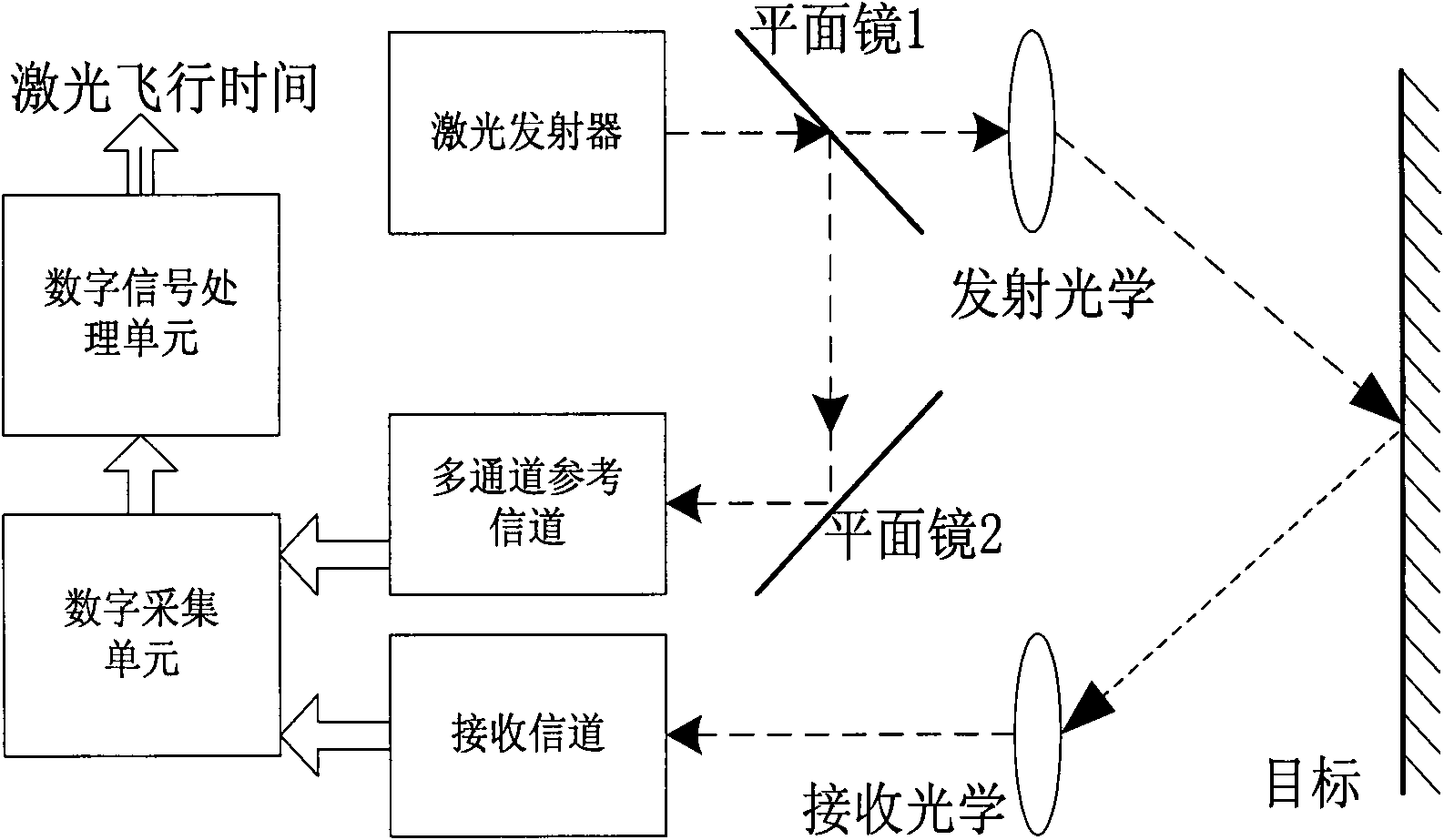
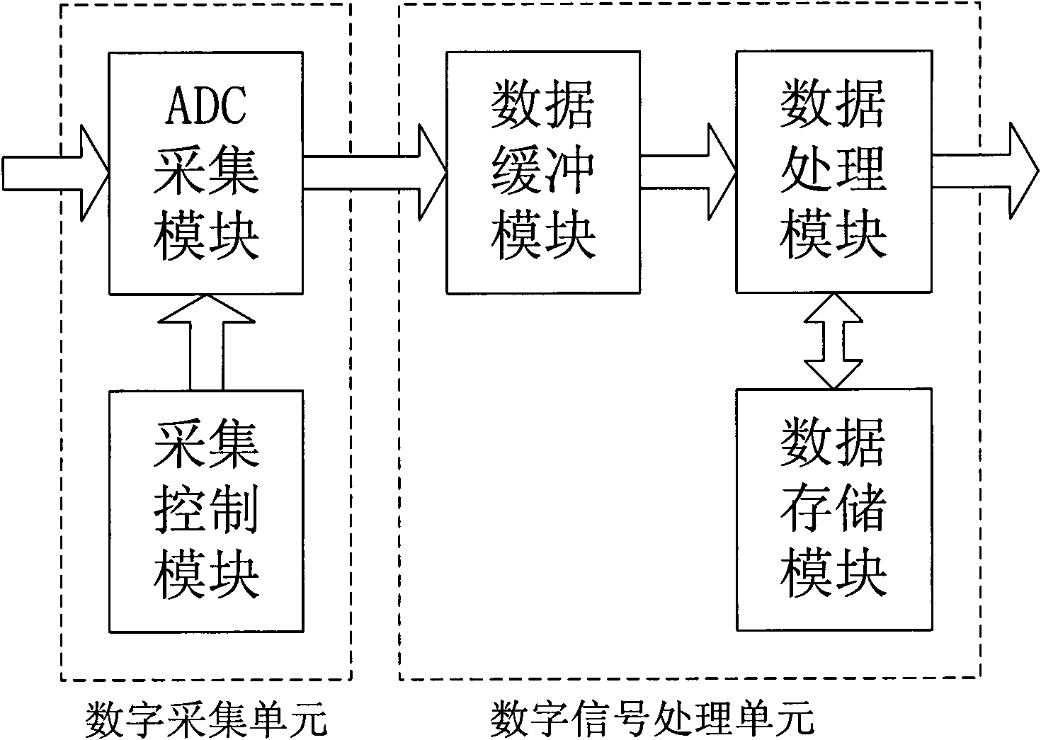
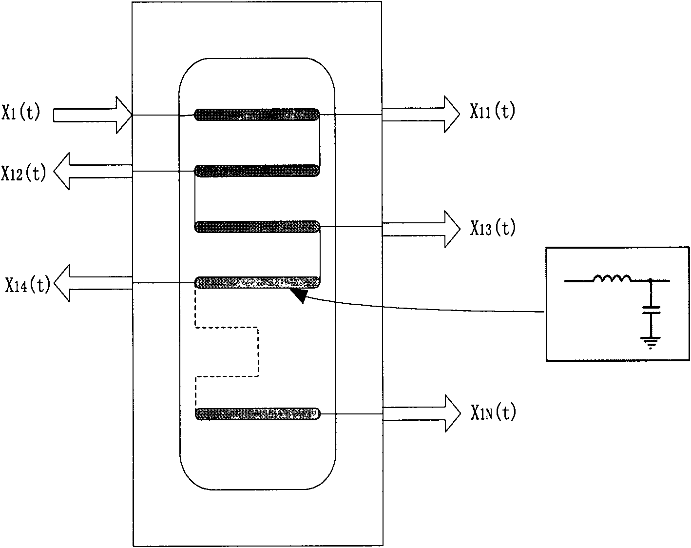
[0023] combine figure 1 , the laser time-of-flight measurement device based on multi-channel delay estimation in the present invention includes two parts: an optical system and an electronic system. The optical system is composed of transmitting optics, receiving optics, first plane mirror 1 and second plane mirror 2; the electronic system is composed of laser transmitter, receiving channel, multi-channel reference channel, digital acquisition unit and mathematical signal processing unit. The optical parameters of the first plane mirror 1 and the second plane mirror 2 are the same, such as a transmittance of 90-98% and a reflectance of 0.5-1%. The first plane mirror 1 is placed in front of the laser transmitter, and its center is 3-5 mm away from the laser transmitter, forming an angle of 45° with the laser transmitter. The second plane mirror 2 is placed in front of the multi-channel reference channel, and its center is 3-5 mm away from the multi-channel reference channel. 3...


PUM


Abstract

The invention discloses a laser time-of-flight measurement device based on multi-channel time delay estimation and a method thereof. The method comprises the following steps: firstly, opening a multi-channel reference channel and a receiving channel immediately when a laser emitter emits a laser beam; secondarily, performing delay-time processing on the signals by the multi-channel reference channel according to a fixed time interval to form multi-channel reference signals; and finally, transmitting the echo signals of the receiving channel and the multi-channel reference signals to a digitalsignal processing unit by a digital collection unit to carry out cross-correlation operation, and correcting the obtained different time delay estimation values by linear polynomial fitting to obtainthe optimal time delay estimation value. The method and the device are completely digitalized; the device is simple; and the method is effective, has small calculation amount and high stability and can effectively improve the measurement accuracy of the laser time-of-flight.

Description

technical field [0001] The invention belongs to the field of laser radar signal processing, in particular to a device and method for measuring laser flight time, which are applied to laser ranging, laser imaging radar and other purposes. Background technique [0002] Laser time-of-flight measurement technology is widely used in laser direct detection applications such as laser ranging and laser imaging radar. The accuracy of laser time-of-flight measurement is directly related to the accuracy of distance measurement and the clarity of distance imaging. [0003] The traditional analog laser time-of-flight measurement is divided into two steps: time discrimination and time interval measurement. Time discrimination is generally to perform simple preprocessing on the laser emission pulse and echo pulse, such as high-pass differentiation, low-pass filtering, etc., and then extract the rising edge of the digital signal at the start and end of the laser through a high-speed compara...

Claims


Application Information

Patent Timeline
IPC IPC(8): G01S7/48G01S7/481
Inventor 陈钱顾国华徐伟
Owner NANJING UNIV OF SCI & TECH
Learn More